I'm always amused to see how DS offers the consumer to choose between problems
View attachment 663207
That second image is of a linear phase filter, the pre-ringing can be easily seen just before the square wave edge transitions.
Sorry, but it is vice versa and similiar to original graph from ebay seller's page.
X = Connection
O = Open
To follow up on this question, I checked with the seller and this is the information he sent me:
"Coaxial: PCM44.1K-192K 24BIT / DOP DSD64
Fiber: PCM44.1K-192K 24BIT / DOP DSD64
IIS / DSD: PCM44.1K-384K 32BIT / DSD64, DSD128, DSD256
IIS / DSD pin definition:
Enter the settings
Digital filter settings
Jumper setting instructions: 1. O = connection; X = disconnect,"
On the other hand, I find that J2 jumper needs to be on for Coaxial SPDIF, and J1 for Optical SPDIF.
Last edited:
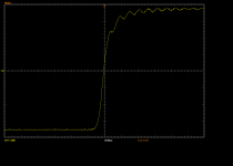
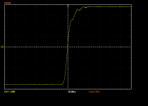
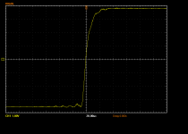
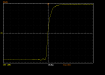
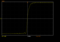
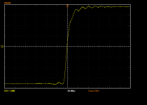
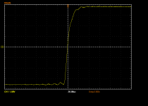
The linear filters look to me like there is pre-ringing. Not for the Apodizing filter though.
What should happen normally is since time flows from left to right in the scope images, any ringing should decay with an exponential envelope as time passes. It would be more obvious with a lower frequency square wave, but the linear phase filters look more flat and symmetrical across the tops, as compared to the other filters which seem to be settling or decaying a little bit as time passes. So, my interpretation of the images is that there is pre-ringing, but I would like the square wave at a little bit lower frequency to see a little better.
What should happen normally is since time flows from left to right in the scope images, any ringing should decay with an exponential envelope as time passes. It would be more obvious with a lower frequency square wave, but the linear phase filters look more flat and symmetrical across the tops, as compared to the other filters which seem to be settling or decaying a little bit as time passes. So, my interpretation of the images is that there is pre-ringing, but I would like the square wave at a little bit lower frequency to see a little better.
Last edited:
Hi guys!
I got my 9038q2m board few days ago (VR1.06). <snip>
Thank you very much for posting the info. I have been thinking of using a passive I/V module, after reading the info posted in the thread on the Signalsyt DSC1 DAC. Personally, an active I/V is too much work (for me) for this board. My plan is to just utilize two transformers and call it a day.
If you don't mind, would you please post some pictures on how to install your transformers onto the board (what components to remove and where to connect). Thank you for your help in advance.
Regards,
My plan is to just utilize two transformers and call it a day.
Two high quality transformers can be rather costly. More than the cost of a couple of high quality op-amps.
Agree. However, the price range for transformers is quite large and I am not going to put an ultra expensive Lundahl on this board. With a transformer, I can rig up a balanced output easily too. An opamp add on module needs another power supply, add more daughter boards etc. That's fine when people enjoy tinkering and experimenting. I used to love that. Don't forget the time that one has to put in too. At this point, I just want minimum fuss to set up the DAC and then just enjoy listening to it (hopefully).
Regards,
Regards,
An opamp add on module needs another power supply, add more daughter boards etc.
Understood. Please let us know it sounds and what transformers you end up with. Thanks.
I also would just mention to anyone reading that one could use the existing +- 15 power for opamps, so no need for a second power supply in that case.
Will do. I am going to place an order after the vendor "reopen". I plan to use this DAC with a XMOS U8 card that I have lying around.
By any chance would you know what is the output voltage of the DAC chip? It is next to impossible to find the technical data of ESS chips. Thanks!
Regards,
By any chance would you know what is the output voltage of the DAC chip? It is next to impossible to find the technical data of ESS chips. Thanks!
Regards,
To follow up on this question, I checked with the seller and this is the information he sent me:
Jumper setting instructions: 1. O = connection; X = disconnect,"[/I]
Well, all I can say... In fact there are no connections called 01-06, 1-6 only... There is no J06 (or J6) for LPF settings at all! Seller does not really knows his own goods. He will soon be waiting to receive less than 5 stars for the discrepancy of the description...
That second image is of a linear phase filter, the pre-ringing can be easily seen just before the square wave edge transitions.
It depends on the sample rate of the source PCM. I have changed LPF to "slow roll-off minimum" = J4 and J5 shorted to GND
Here is comparison: 48k vs 192k (2kHz square)
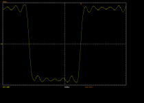
48k
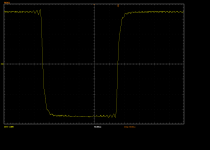
192k
And here is near-edge zone of 20Hz square (SR=192k)
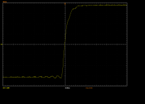
Last edited:
By any chance would you know what is the output voltage of the DAC chip?
The AVCC+ power rail is +3.3 volts. I can't measure anything on my board right now as it is all apart. Can't be more than around 3 volts though.
More important is probably how much current it can put out. The sound quality is higher if the DAC outputs are run into a short to ground. That means the secondary of the transformer should be a short and you should have a current stage there to convert to voltage. Otherwise, if you connect the transformer to a high impedance input that means the DAC is still working in voltage mode. If that's what you want, you may as well use it without any modification at all. Well, unless maybe you like the sound of transformers added in. Some of them can make a little distortion that some people like the sound of.
Last edited:
It depends on the sample rate of the source PCM. I have changed LPF to "slow roll-off minimum" = J4 and J5 shorted to GND
Here is comparison: 48k vs 192k (2kHz square)
Thanks for doing that. It sure looks like linear phase pre-ringing to me.
Say, I wonder if the seller was trying to say the jumper settings are inverted only for the filters?
In that case might we be looking at a linear filter? Just wondering. It would probably be helpful to many people wanting to use these boards if we could verify the filter jumper settings are correct or inverted.
If you don't mind, would you please post some pictures on how to install your transformers onto the board (what components to remove and where to connect). Thank you for your help in advance.
It is very simple procedure.
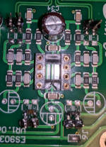
All you need is just to remove 4x6.2kOhms (labeled as 6201) resistors which are between 9038's diff outputs and OPs. Primary coil of the transformer should be connected to +and- of the channel. OPamp is better to remove from the board to save power. And if you want to use RCAs of the board, it is needed to remove 2x(100and47k) Oms resistors to connect secondaries between signal and GND (of the RCAs in fact). Between the PLS pins of secondary coils I have soldered 10k (value of that loaded resistors depends on transformer specs).
Two high quality transformers can be rather costly. More than the cost of a couple of high quality op-amps.
Agree. However, the price range for transformers is quite large and I am not going to put an ultra expensive Lundahl on this board.
It is true. Transformer can not cost less than OPs - it is mostly handmade thing. But for me personally there is no any chances for any OPs to make i/v conversion better than current transformer. In terms of current transformers... It is very important not to confuse current transformers with voltage transformers. Current transformer must have as lower DC resistance of the primary coil as it can, to become really current-mode transformer. In other words, the curernt of the DAC's signal must be shorted to the ground to provide best SQ. And only the inductance as a reactive resistance should transform that alternating current from the primary coil to secondary. In real world it is very difficult task to get low windings (and DC resistance) with enough level of inductance. Browse yourself and try to find out similiar to "mine" transformer specs? I'm afraid that Lundahl transformers are totaly going out of that specs - it is pure voltage transformers. In this case mostly all the conversion happens inside active resistance of primary coil (or even separate resistor in parallel with primary coil of the transformer). Sound is forming outside of the transformer in this case. To safe the output of the DAC from the voltage applied to it during i\v conversion almost forever is used a small value resistor in parallel with primary coil (small voltage of signal as result) and then to make the signal louder, a huge amount of turns ratio (10-20 times!) is applied in transformer. It simply kills the sound. In that case it is really better to use OPs I guess. As far as I know there is only one model in the market at all that can be compared with "my" transformers, but "my" are better at least by specs. I mean Sowter 9545 model, which is captured by AudioNote and not presented on ready for sell market at least for now. Again: DC=5Ohm, Inductance=16H, FR: -0.5dB 20-100k, output level ~8Vpp, turns ratio 1:3.5
The AVCC+ power rail is +3.3 volts.
Thanks!
It is very simple procedure.
All you need is just to remove 4x6.2kOhms (labeled as 6201) resistors which are between 9038's diff outputs and OPs. Primary coil of the transformer should be connected to +and- of the channel. OPamp is better to remove from the board to save power. And if you want to use RCAs of the board, it is needed to remove 2x(100and47k) Oms resistors to connect secondaries between signal and GND (of the RCAs in fact). Between the PLS pins of secondary coils I have soldered 10k (value of that loaded resistors depends on transformer specs).
View attachment 663365
Thanks! I guess I'll have a better idea when I get the board. If the tracks on the board are easy to trace, the connections should be obvious.
Regards,
Some info on the Sowter transformers:
Sowter Type 9545 DAC INTERFACE TRANSFORMER
1465 DAC Interface Transformer
DAC OUTPUT TRANSFORMERS
Looks like 1465 is the closest to the 9545, and it's only about 110 British Pounds for one. They say it is the 100 ohm or 200 ohm resistor that does the IV conversion, and the transformer provides galvanic isolation. They also say the IV resistor can be attached at the secondary, but with it's value increased according to the impedance ratio of the transformer.
Looks like 1465 is the closest to the 9545, and it's only about 110 British Pounds for one. They say it is the 100 ohm or 200 ohm resistor that does the IV conversion, and the transformer provides galvanic isolation. They also say the IV resistor can be attached at the secondary, but with it's value increased according to the impedance ratio of the transformer.
In fact, due to lost of inductance of primary coil (do not forget that you still want to get low DC resistance to ensure that the sound will forming inside the transformer and to get enough "line" level of the signal) the output level will be limited in LF to get linear FR. In other case there will be lost in LF compared to upper freqs. The main goal - is to get as louder signal as it possible from DAC with saving of linear FR. With 1465 or 9545 you can get linear FR but the level is limited by inductance of primary. DC resistance is just an indicator, because after it there is another problem - capacitance, that will acts like HPF - another side of a coin. It is very complex task enough to make right i/v transformer

Say, I wonder if the seller was trying to say the jumper settings are inverted only for the filters?
Seems to be true.
I have no time right now to post more today. I have to go sleep, because here it is 3:40 AM already

But I captured all the variations of LPFs. I will post them by order of the graph mentioned. To get know who is who, just read the name of files...
- Home
- Source & Line
- Digital Line Level
- ES9038Q2M Board