Do you know what part is to be used? And what pitch are the pads?
It would appear from the layout the array should be no harder to solder than the WM8804.
Ken
I'm sure the designer will pop in and clarify. In the mean time here is my guess at what package that resistor pack is. It looks like it is a 1206 wide 4 resistor pack. Maybe it is the size up from that, hard to tell.
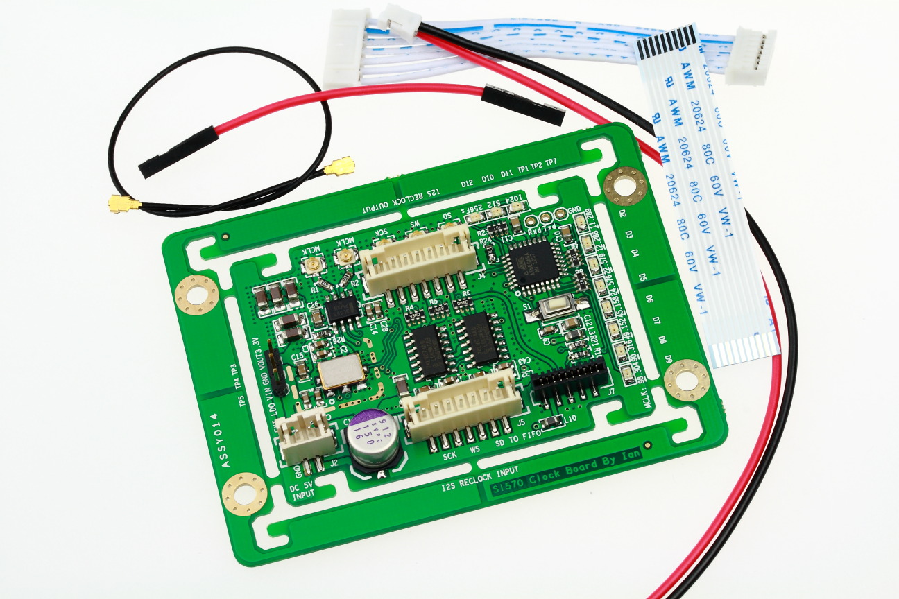
Here is a pic of another forum project with a pre-soldered resistor pack on it. (Ian takes good photos so I chose his simply because I knew the pics would be clear). See R4, R5, R6 ... they are harder to solder because they don't have individual leads out like the soic chips do.
http://www.diyaudio.com/forums/attachments/group-buys/330882d1361051302-ian-asynchronous-i2s-s-pdif-fifo-kit-group-buy-14_si570clockboard.jpg
Other than that resistor pack being a challenge for SMD beginners, the certainly layout looks tidy!
As an constructive alternative option for those keen to do a bit more DIY SMD work here is a project that lets you have PID control of a cheap toaster oven that may make some of this soldering a touch easier, though you've still got to be steady with the solder paste syringe and you need to be careful which toaster oven you select as they won't all get hot enough for Pb-free solder paste. I have a toaster oven here and am just waiting on the controller to arrive in the mail next week
") . I chose to build one of these because I have a few projects where I want to be able to solder my own QFN and resistor packs and for now I can't justify the expense of a hot air rework station (well not the one I would like anyway).
. I chose to build one of these because I have a few projects where I want to be able to solder my own QFN and resistor packs and for now I can't justify the expense of a hot air rework station (well not the one I would like anyway).To the poster earlier considering using this for an 8ch build. You should consider how your clocking will work in that configuration. The mini-sharc has no clock and is the slave on the mclk line. You will need to output the mclk to the minisharc and distribute it to each clock board. This won't be a trivial exercise and you may need to roll your own pcb with clock distribution buffers. Not simple but not impossible, do your research though because you may find that there are simpler options out there for your specific project.
Cheers,
Chris
Last edited:
I agree with Ken, the resistor array won't be harder to solder vs WM8804.
And Yes qusp, a short circuit will be hard to debug.
I remember smd diodes in "The Wire HeadPhone" PSU, not really easy, but it was a smallest GB and more skilled people involved.
My opinion : Ain't necessary to add difficulties as it's a large audience project.
That's why there will be testing & evaluation done before the final PCB design.
All your inputs/remarks are welcome
Read carefully Subbus post. PCB pic is a sample intended to be changed and modified...
Phil
And Yes qusp, a short circuit will be hard to debug.
I remember smd diodes in "The Wire HeadPhone" PSU, not really easy, but it was a smallest GB and more skilled people involved.
My opinion : Ain't necessary to add difficulties as it's a large audience project.
That's why there will be testing & evaluation done before the final PCB design.
All your inputs/remarks are welcome
Read carefully Subbus post. PCB pic is a sample intended to be changed and modified...
Just to spice up JPs post, here is a sample of what is going to be ordered this weekend for evaluation and testing. More news to follow.
Cheers!
Subbu
Phil
Last edited:
Here is a pic of another forum project with a pre-soldered resistor pack on it. (Ian takes good photos so I chose his simply because I knew the pics would be clear). See R4, R5, R6 ... they are harder to solder because they don't have individual leads out like the soic chips do.
http://www.diyaudio.com/forums/attachments/group-buys/330882d1361051302-ian-asynchronous-i2s-s-pdif-fifo-kit-group-buy-14_si570clockboard.jpg
Cheers,
Chris
Some VERY tidy soldering on that board Chris - The resistor array up against the QFP must have been quite a challenge though!
However, for "our" board I think everything looks doable without too much trouble.
Ken
Just curious, is the use of SPDIF and I2S mutually exclusive?
I am greedy and want the DAC can connect to more than one digital source.
You can use a quad channels 2:1 switch like the OTTO2 for I2S switching.
Last edited:
Subbu is the one adapting the design for BAL. We both have jobs etc so we struggle along and try to do a V3 in our free time. When a BAL version is ready (if there wil be one at all) Subbu will say so.
I plan on a redesign of the BAL version as soon as we complete the SE version. Priority now is to get the SE out as folks have been waiting long. Hopefully I will find some time to work on the BAL version once SE is completed given that personal & work commitments have been taking away all the free time recently.
the resistor array is good idea, but its definitely the hardest part on the board to solder and i'm not sure its doing much good how its placed or was it a money saving thing? they are only JUST hand solderable with a normal iron and very easy to create a short circuit without being able to see it easily, do you really need it? have you got much experience soldering them yourself Subbu? for easy soldering they really need reflow or hot air IMO; itrs doable, but a pita with an iron and i've got quite a lot of SMD experience.
On the Resistor pack, it was chosen for better layout of tracks and to avoid layer change. The options thought were either to use a 0603 or resistor pack. Based on the prototype it is possible this might change if we feel its difficult to solder the RP.
Regards,
Subbu
You can use a quad channels 2:1 switch like the OTTO2 for I2S switching.
Thank you for the information~
In fact, I have the option of building one DAC with SPDIF and the other DAC with I2S.
I have ordered several PCBs.
Still in test phase but BG N or NX series still are my personal favorites. Availability is bad so there are alternatives tested. We will publish when things are interesting enough.
JP, thank you for the hard work~
If possible, I prefer more readily available parts than BG caps.
These days i had the oportunity to listen to older version DAC (previous group buy) but powered from a MC7805. What improvement should i expect using the low noise regulator designed for this DAC ?
I built my v2 dac and had it running on a cheap and dirty 5v initially before I built the psu. Quite a dramatic improvement tbh - more low level detail , tighter bass are two things I noticed
Nope Hopefully it shouldn't be too much longer, but it's done when it's done.
Hopefully it shouldn't be too much longer, but it's done when it's done.Hi To all on this thread - just added my name to the spreadsheet . . .
Can someone tell me when this GB will happen
many thanks
mike
- Status
- This old topic is closed. If you want to reopen this topic, contact a moderator using the "Report Post" button.
- Home
- Group Buys
- ES9023 / WM8804 S/PDIF "Subbu DAC V3" GB Interest