Check the orientation of Q2 (the 50Mhz oscillator). If you parts is identical to the BOM, it looks like oriented wrong. You can take a look at my picture in post 303.Hi Korben.
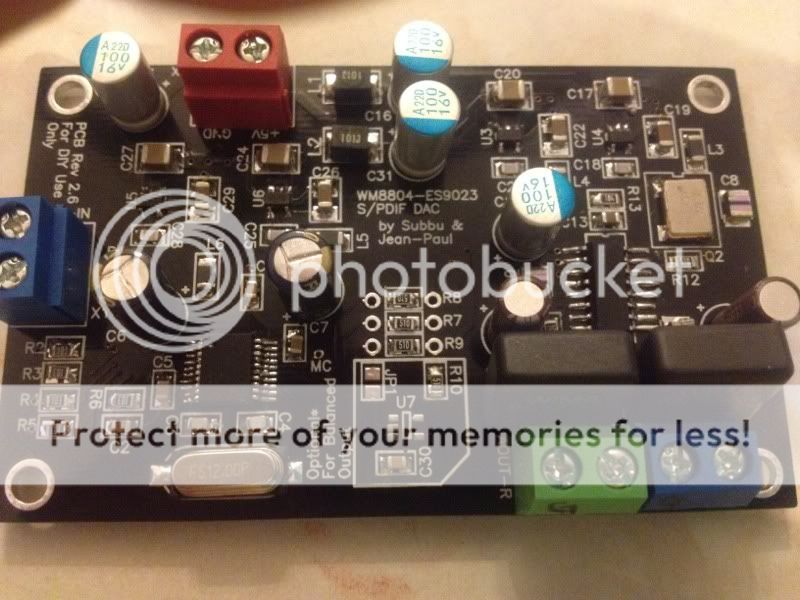
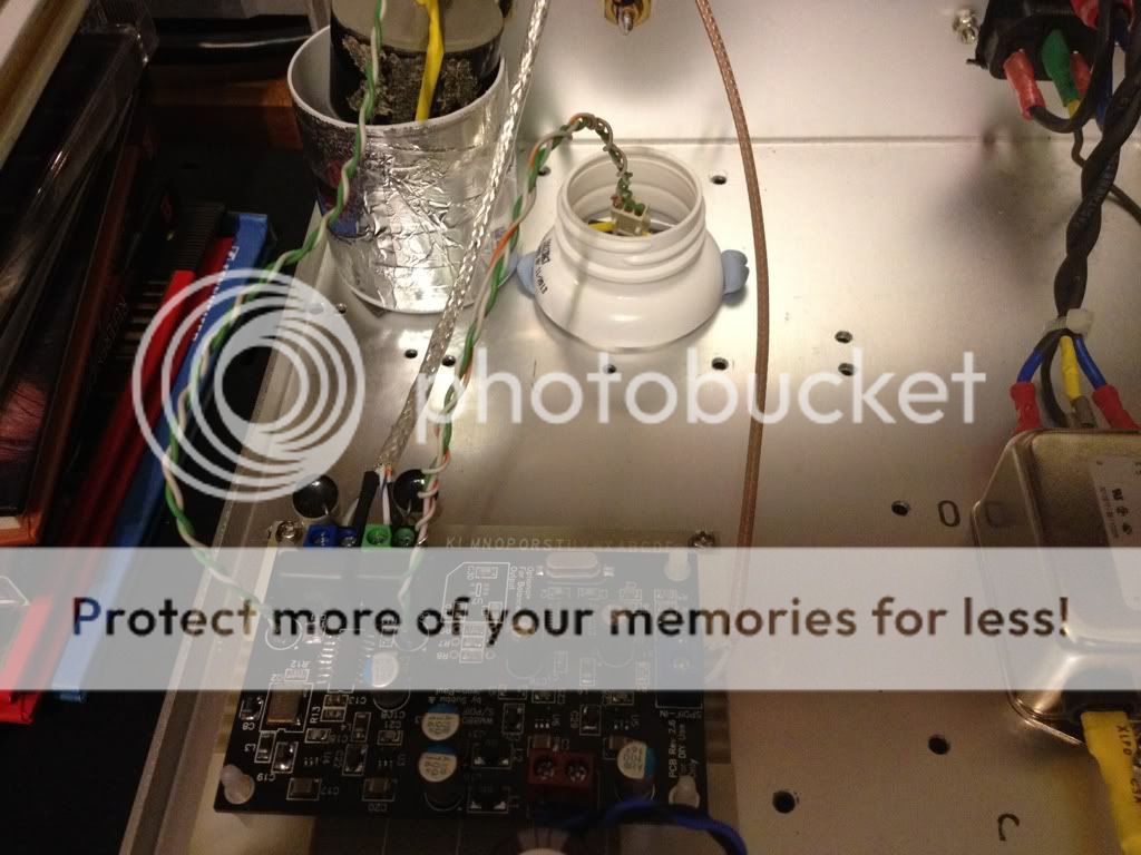
My psu is a Salas V1.0 and my source is a Pionner PD D6 J. I have attached a pic. Any suggestions are welcome
Hi all.
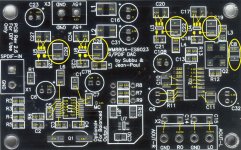
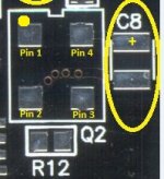
Did some voltage measurments using the very useful picture posted by korben:
c29=3.30
c26=3.23 (low?)
c22=3.57
c19=3.29
c8=3.28
c1=1.60
c7=3.22
c5=3.30
c28=1.93
c25=1.88
c2=3.22
c21=2.23
c3=0.53
c4=0.82
c10=3.56
c13=3.52
I have pure mode off in PD D6 and for Q2 orientation i attached a picture showing the dot on the surface.
Im using lm7805 to feed the dac
Attachments
Last edited:
Hi skouliki
Q2 is in right position as shown in your pic.
Measures seems to be Ok from those you've measured.
Could you please test voltage on : Q2 - C10 - C10b - C11 - C32 - C9 - R11
Carrefuly check pins from ES9023.
WM8804 seems Ok, but check it too.
How much DC offset at the output ?
Hope this helps
Phil
Q2 is in right position as shown in your pic.
Measures seems to be Ok from those you've measured.
Could you please test voltage on : Q2 - C10 - C10b - C11 - C32 - C9 - R11
Carrefuly check pins from ES9023.
WM8804 seems Ok, but check it too.
How much DC offset at the output ?
Hope this helps
Phil
HI, here is my building report....
I finish my board yesterday. I was following Jan-Paul instructions, first i check voltages from regulators, then i solder 2 IC's and check voltage and curent. Voltages was OK and total curent on 5V is about 50ma. DAC is not working until i close jumper. When I close the jumper i hear music from speaker, maybe Skoulike have the same problem. I see on his pic that jumper is open and there is no U7 and 2 other components.
First sound impression is promising, i try on labaratory power supply and my test speakers, CD is marantz cd52mk2. I'll write more about sound when i receive and finish PSU boards and put everything in metal case after that i'll do more listening tests.
I've built 2 dac boards, both of which work, so I'll add my suggestions. First, if one is building a single ended DAC (not balanced) then the parts U7, R10, C30, and JP1 are not needed. I'm not sure why tome had better results shorting JP1.. . . When I close the jumper i hear music from speaker, maybe Skoulike have the same problem. I see on his pic that jumper is open and there is no U7 and 2 other components . . .
Tome's comments did make me think that perhaps Skoulike had forgotten about the parts on the other side of the board. Parts R14, R15, and C12 are on the back of the board. In particular, if you don't add R14 and R15 (zero ohm jumpers) then the outputs won't be connected. Please check this.
---Gary
HI, here is my building report....
I finish my board yesterday. I was following Jan-Paul instructions, first i check voltages from regulators, then i solder 2 IC's and check voltage and curent. Voltages was OK and total curent on 5V is about 50ma. DAC is not working until i close jumper. When I close the jumper i hear music from speaker, maybe Skoulike have the same problem. I see on his pic that jumper is open and there is no U7 and 2 other components.
First sound impression is promising, i try on labaratory power supply and my test speakers, CD is marantz cd52mk2. I'll write more about sound when i receive and finish PSU boards and put everything in metal case after that i'll do more listening tests.
Hi,
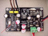
I didn't close the jumper and I have no problem with the DAC. The dot on the crystal should be positioned further away from the analog output. Trace the voltage on the on chip power pin and the Neg pin. Check if there is any Vac from the output pin on the chip while you have digital signal going in.
I still didn't cean up the flux.
Last edited:
Skylab - don't forget to change the polarity of C32. In your photograph, it's shown with the incorrect polarity.I still didn't cean up the flux.
See Korben's great photo for the correct orientation.
---Gary
Attachments

Skylab - don't forget to change the polarity of C32. In your photograph, it's shown with the incorrect polarity.
See Korben's great photo for the correct orientation.
---Gary
Yep,
Very good eye, that was an old photo, I have changed the polarity already but I have also been testing with a solen MKP in C8(1.5uf) and C32(22uf).
Thanks GaryB for your informations.
I've mentionned that SE version (Unbalanced) don't need U7, R10, C30, and JP1 to be populated.
The EU Parts GB provides those parts to SE kits buyers while they are useless (my mistake)
For Q2 orientation, check this one attached.
I've mentionned that SE version (Unbalanced) don't need U7, R10, C30, and JP1 to be populated.
The EU Parts GB provides those parts to SE kits buyers while they are useless (my mistake)
For Q2 orientation, check this one attached.
Attachments
Last edited:
Will try to explain
I solder all the components including the U7. There was no music after switch on. When I measured the voltages I accidentally touched U7, then I heard the noise with the music in the background. I closed jumper and I got a clean sound without noise. When I open jumper I get the same as before, there is no sound. Tomorrow I will remove the U7 and seeing what will happen.
I solder all the components including the U7. There was no music after switch on. When I measured the voltages I accidentally touched U7, then I heard the noise with the music in the background. I closed jumper and I got a clean sound without noise. When I open jumper I get the same as before, there is no sound. Tomorrow I will remove the U7 and seeing what will happen.
Yep,
Very good eye, that was an old photo, I have changed the polarity already but I have also been testing with a solen MKP in C8(1.5uf) and C32(22uf).
Uh oh !
Some more measurments. Orientation of numbers as per Korben's picture:
U3: 3.57
L4:
3.57
3.56
R13:
3.56 3.52
C13:
0.00 3.52
DAC:
1.58--- ---0.00
1.62--- ---3.52
0.03--- ---0.00
------- ---1.66
------- ---0.00
------- ---(-3.34)
C10:
0.00
3.56
R11:
1.14
0.00
C11:
-1.70
1.73
Q2:
3.25 3.28
0.00 1.66
C9:
1.14
0.00
C32:
-3.34
0.00
C10b:
3.56 0.00
Attachments

Last edited:
- Status
- This old topic is closed. If you want to reopen this topic, contact a moderator using the "Report Post" button.
- Home
- Group Buys
- ES9023 / WM8804 S/PDIF DAC Group Buy