So the parts concerned by Tantalum replacement are :
1° - C19, C22, C26, C29 and C8 for SE
Would this one be a good candidate : 293D475X9010B8T Vishay/Sprague | Mouser
Please confirm Jean Paul
Phil
PS : Yes, changes in BOM, schematic and build guide are welcome as those parts are polarized.
Good candidate. Can't comment on the balanced version but 4.7 µF tantalium for all used 4.7 µF caps after the regs and for C8. Simple. Effective.
I see the difficulty in keeping things in sync Subbu and I being on 2 different continents with different timezones and different lives and work etc. and how to publish changes/improvements along the way ? Should be a central point that can change dynamically. Yeah a website, heard your thoughts. I can't do it as I don't have that experience and the time and I simply don't want to do it as I better devote my time to designing a new DAC. Job description was: design DAC, design PCB, build it, test it, improve it. That's what I was hired for
")
Last edited:
Jean Paul, you answer was awaited as I'm managing the EU Parts GB...
I'm trying to do my best in this project, and as there are some money left, I'll place the order ASAP to Mouser's - SE & BAL - for all DIYer's who subscribed to the EU GB.
Could you please check it twice
Next project : USB to I2S... sorry, I've forget you aren't a USB guy
I'm trying to do my best in this project, and as there are some money left, I'll place the order ASAP to Mouser's - SE & BAL - for all DIYer's who subscribed to the EU GB.
Could you please check it twice
Next project : USB to I2S... sorry, I've forget you aren't a USB guy
Can't tell much but it will be USB + SPDIF + I2S + DAC and the PSU on one single board with connectors all on the PCB so only 115 V/230 V wiring. It will not be a Group Buy effort, sorry.
While I don't like USB the rest of the world does so I will adapt. Off to bed now, will check twice tomorrow.
While I don't like USB the rest of the world does so I will adapt. Off to bed now, will check twice tomorrow.
Last edited:
Marlowe, why don't you put the diodes inside the same box with the DAC? so that from the PSU Box to the DAC Box the power transmission is in AC...
Is there advantage of carry it in DC over AC? I thought carry electricity in the longer cable would be beneficial in AC, since AC do not induce electro magnetic stray....?
Hi dw1narso,
In fact, the cable is a long cable. The length is only 25cm.
I did not try to carry the power over AC. I found most power separated commercial productions transmission the power over DC (filtered or non-filtered).
Hi,
I would recommend to put the smoother cap in the PSU box. The way you have it now, the charging pulses to the smoother cap are carried over the long PSU cable. Feed the DAC the raw DC and regulate it locally.
Ray
Marlowe I missed your post. Neat build again but Ray has a very good point regarding the charge pulses. Either go for a one box solution or make a separate DC supply. AC does pick up RF more easy than DC IMHO. So DC is the way to go. As a sidenote: switching DC is not favorable for known reasons. And I would not put my money on SC transformers. You were telling that the EUVL DAC and ours sound alike with all these nice parts on the EUVL DAC ? That is a positive message. Will you be tweaking our DAC too ? Please let us know how things develop.
And Syklab is called Syklab not Skylab but that can have been an error on his part
Hi Ray and jean-paul,
Yes, filtering the DC in the power box may be good, but the power box is too small to fit additional capacitors.
In my other projects, I compared filtering the DC in the power box with filtering the DC in the load box. The difference is insignificant.
By the way, there is no smooth capacitors in 47 Lab power modules as well.
I ordered two sets of the WM8804/ES9023. My plan is to tweak on one set and keep the other set on "default setting" for reference.
Hi Syklab,
I am sorry I misspelled your name.
Last edited:
My power supply isn't
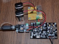
I threw together a PS and hooked everything up last night and got no sound. I found the voltage from the PS started at just below 5V, then dropped quickly. The decrease slowed as it approached 3V. Checked it with the scope there's no oscillation. It's a super simple design: An LM7805 with a 0.22uF ceramic cap to ground on the left pin and a 0.1uF polyester film cap to ground on the right pin. Power is a 9V battery. Regulator is well heatsinked and gets warm, but not hot. I've tried a few batteries, and the problem is not a dead battery.
So do I blame the lack of sound on the DAC or the PS? or maybe my TOSLINK module? Will the DAC work at all with 3V to 4V? I've ordered the Velleman kit, which should arrive by the end of the week.
Blame yourself
This is not a project for SMD beginners. If you want to build it then build it as recommended which is not with a 9 V battery. I think the current is too much for a 9 V battery (this would be the best error of all as it is reversible easily) or there are shorts on the PCB or defective/overheated parts. Could be anything. TOSLINK module ? How is it connected ? To one of the onboard regs ? (oh no). The DAC can't work with 3 V as the regs need to deliver 3.3 and 3.6 V. But 4 V is no problem.Pics would help considering all possibilities.
Last edited:
Hi Jean Paul, I'm back with this point
Parts concerned by Tantalum replacement are :
1° - C19, C22, C26, C29 and C8 for SE
2° - C19, C22, C26 and C8 for BAL
Would this one be a good candidate : http://fr.mouser.com/ProductDetail/...=sGAEpiMZZMuEN2agSAc2pj8MbHwJGci9U2mVu6qTaAc=
Verdict your Emeritus ?
Parts concerned by Tantalum replacement are :
1° - C19, C22, C26, C29 and C8 for SE
2° - C19, C22, C26 and C8 for BAL
Would this one be a good candidate : http://fr.mouser.com/ProductDetail/...=sGAEpiMZZMuEN2agSAc2pj8MbHwJGci9U2mVu6qTaAc=
Verdict your Emeritus ?
Last edited:
Hi that cap is OK too.
Parts concerned by Tantalum replacement are :
1° - C19, C22, C26, C29 and C8 for SE
2° - C19, C22, C26 and C8 for BAL
Confirmed but I have to tell I did not adapt the design for balanced use. Never built one but it seems OK to me.
To all: the output caps for MIC5205 should be not too low ESR so no PPS or ceramic but please use tants 4.7 µF 10 or 16 V. Same for C8.
Last edited:
The TOSLINK is just a TOSLINK to S/PDIF converter: photons to electrons. TOSLINK Optical Input to S/PDIF Module | eBay I measured output as 1V peak-to peak, seen in the oscilloscope trace included in the photo.
If I can't use a 9V battery for a power supply I'll just wait for my Velleman kit to come in.
If I can't use a 9V battery for a power supply I'll just wait for my Velleman kit to come in.
Attachments
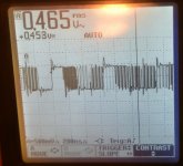
The TOSLINK is just a TOSLINK to S/PDIF converter: photons to electrons. TOSLINK Optical Input to S/PDIF Module | eBay I measured output as 1V peak-to peak, seen in the oscilloscope trace included in the photo.
If I can't use a 9V battery for a power supply I'll just wait for my Velleman kit to come in.
Can you take a better picture of the dac? Check the input and output voltage on each regulator.
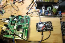
got one board working
ian's reclcoker as input, salas bib as power supply
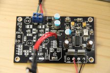
I burnt the other board so I cannot complete the balanced mode.
lessons learned (especially when dealing with smd components):
1) don't populate everything and then start testing. this is what I did with the first board and could not find cause of failure. started desoldering and some traces were pulled off. this board is bricked
2) populate sections and test individually. In this case, the regulators can be populated and tested. once measurements are acceptable, solder the L components to each section I did this for the second board for the regs for dac and clock sections.
Thanks for this board as this is probably my best cost-effective dac ever built. Sound is very detailed and precise. Wish I had another board to test with balanced config. NOt using the spdif input section as you can see.
If ever there is a second board designed, please allow for external clock support.
Note: if anybody has an extra board to sell, please let me know.
regards
ian's reclcoker as input, salas bib as power supply
I burnt the other board so I cannot complete the balanced mode.
lessons learned (especially when dealing with smd components):
1) don't populate everything and then start testing. this is what I did with the first board and could not find cause of failure. started desoldering and some traces were pulled off. this board is bricked
2) populate sections and test individually. In this case, the regulators can be populated and tested. once measurements are acceptable, solder the L components to each section I did this for the second board for the regs for dac and clock sections.
Thanks for this board as this is probably my best cost-effective dac ever built. Sound is very detailed and precise. Wish I had another board to test with balanced config. NOt using the spdif input section as you can see.
If ever there is a second board designed, please allow for external clock support.
Note: if anybody has an extra board to sell, please let me know.
regards
Attachments
got one board working
ian's reclcoker as input, salas bib as power supply
I burnt the other board so I cannot complete the balanced mode.
lessons learned (especially when dealing with smd components):
1) don't populate everything and then start testing. this is what I did with the first board and could not find cause of failure. started desoldering and some traces were pulled off. this board is bricked
2) populate sections and test individually. In this case, the regulators can be populated and tested. once measurements are acceptable, solder the L components to each section I did this for the second board for the regs for dac and clock sections.
Thanks for this board as this is probably my best cost-effective dac ever built. Sound is very detailed and precise. Wish I had another board to test with balanced config. NOt using the spdif input section as you can see.
If ever there is a second board designed, please allow for external clock support.
Note: if anybody has an extra board to sell, please let me know.
regards
Hi what is ians reclocker ? It should not be a surpise that first soldering the regs and surrounding parts and then test it is normal procedure. Anyhow you got it working.
There won't be a new group buy revision with external clock support, sorry. And to be honest I don't see the benefit of added wiring, power supply and all problems that come with it. Choose the best XO that you can find and solder it to the board and you're done.
I am glad you like it !
Ian's reclocker ia an i2s fifo dedvice
thread:
http://www.diyaudio.com/forums/digi...ifo-project-ultimate-weapon-fight-jitter.html
J-P: is there any way I can get another board.
thanks again for this GB. its working fabulously.
thread:
http://www.diyaudio.com/forums/digi...ifo-project-ultimate-weapon-fight-jitter.html
J-P: is there any way I can get another board.
thanks again for this GB. its working fabulously.
Do if you like but much has already been covered here. Readability is not optimal in a big thread so I understand what you're heading at. I will try to participate in a new thread but in a few weeks I will be busy with other issues and I will be working on a new (even better ) design when time permits.
I guess not many new technical issues will arise. The design is proven to be reasonably easy to build, it is good functioning and very good sounding. Time to move on. We tried to do our best to make this possible but made some errors while doing so. Sorry for that. Enjoy the DAC !
) design when time permits.I guess not many new technical issues will arise. The design is proven to be reasonably easy to build, it is good functioning and very good sounding. Time to move on. We tried to do our best to make this possible but made some errors while doing so. Sorry for that. Enjoy the DAC !
Last edited:
- Status
- This old topic is closed. If you want to reopen this topic, contact a moderator using the "Report Post" button.
- Home
- Group Buys
- ES9023 / WM8804 S/PDIF DAC Group Buy