in my opinion ES9023 works better with a 50 Mhz (async) clock tied as short as possible to it's MCLCK input instead of the master clock coming from the I2S signals (CM6631or XMOS) ; this way a pattented jitter rejection is also possible (maybe due to reclocking inside the chip with this external clock?)
I agree. What xo do you use ? I try before with Epson SAW. http://www.diyaudio.com/forums/digi...9023-te7022-24-96-usb-dac-14.html#post3387896
Some ppl say synch is better. Ears are different eh ?")
But this amp is limit so the amp must be improved or maybe the part is wasted. I think already reach the limit. Sound has correct tone balance, and dynamic, but quiet piano is not good.... loud rock is great.
I see the amp is missing an output filter (10R + 0.7uH) in the datasheet. Also the supply routing have one shared ground return. Decoupling is poor also. Datasheet says this can cause distortion so I try to fix this as the next job.
Some ppl say synch is better. Ears are different eh ?
But this amp is limit so the amp must be improved or maybe the part is wasted. I think already reach the limit. Sound has correct tone balance, and dynamic, but quiet piano is not good.... loud rock is great.
I see the amp is missing an output filter (10R + 0.7uH) in the datasheet. Also the supply routing have one shared ground return. Decoupling is poor also. Datasheet says this can cause distortion so I try to fix this as the next job.
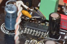
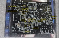
"to improve system performance as well as eliminate possible oscillations, the LM4766 should have its supply leads bypassed with low-inductance capacitors having short leads that are located close to the package terminals. Inadequate power supply bypassing will manifest itself by a low frequency oscillation known as “motorboating” or by high frequency instabilities. These instabilities can be eliminated through multiple bypassing utilizing a large tantalum or electrolytic capacitor (10μF or larger) which is used to absorb low frequency variations and a small ceramic capacitor (0.1μF) to prevent any high frequency feedback through the power supply lines."
I add 10uF SilmicII 35V and 100nF X7R 50V in pair across 3 supply lines on chip pins. 2 (VCC) to 5 (gnd), 4 (VEE) to 5(gnd) and 15 (VCC) to gnd. I use wire through a via on pin 5 (ground) to bottom side of the pcb. I cut trace between pin 5 and 10, and add wire from pin 5 to star ground for separating the ground return.
Sound is better, but still the quiet piano is not nice. For example, Adele, Someone Like You. Vocals, bass, etc all very good. high quiet piano is little bit distorted.
I think it must be the DAC or digital circuit. So I try you idea Mr Hobbit - lower digital volume. This solves the problem. THANK YOU ! So I must try other R8 ? Or check digital circuit ? -4dB is enough.
I add 10uF SilmicII 35V and 100nF X7R 50V in pair across 3 supply lines on chip pins. 2 (VCC) to 5 (gnd), 4 (VEE) to 5(gnd) and 15 (VCC) to gnd. I use wire through a via on pin 5 (ground) to bottom side of the pcb. I cut trace between pin 5 and 10, and add wire from pin 5 to star ground for separating the ground return.
Sound is better, but still the quiet piano is not nice.
For example, Adele, Someone Like You. Vocals, bass, etc all very good. high quiet piano is little bit distorted. I think it must be the DAC or digital circuit. So I try you idea Mr Hobbit - lower digital volume. This solves the problem. THANK YOU ! So I must try other R8 ? Or check digital circuit ? -4dB is enough.
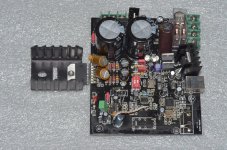
I make the output coils for the amp.
The Inductor
19 turns, 18awg, 7.5mm diameter = 0.7uH + 12R parallel. It have no effect I can hear.
I try 3 different DACs on line in, small distortion is the same for all. None have such distortion.
I try bigger toroid transformer. Sound is little better but small distortion is same.
Finally, I add 470uF across VCC VEE etc. No difference.
I think there is no more to try. Except remove amp and fit a good one.
The bass is good so maybe it can be used for bi-amping project with class-A amp for treble.
I am finished playing. I find that CS8421 is good but LM4766 not acceptable to me.
Hi,
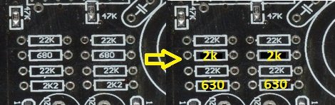
I fix the distortion. There is too much gain. The Rf/Ri is 23K/630 in the kit so Av = 37 . Now it is 23K/1.2K so Av = 20. Input is 2K/23K from 2V rms, so input is 1.9V max. Output Max is 20 x 1.9V = 38V rms. It is already higher than the power supply.
Now at the last I can say I am satisfied with the sound quality.
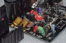
I replace the regulators. 2.5V adp151 and 2 3.3V LP5907. At first the sound is bad = resonating vocal. The LP5907 datasheet says output capacitance is max 10uF but I have many 47uF Oscon. I replace Oscon with 10uF Panasonic and then it is smooth.
I remove the input/output circuit, relay, LED, etc, and cut all traces. ES9023 is connect direct to volume control pins. It seems to not make a difference.
I use ADUM4160 usb isolator always for this. USB 5V only for LED and relay. I check the USB ground and it is not connect to DAC ground, so it can be easy to fit ADUM to this DAC.
Sound quality is great. And for no music, there is normal very quiet amp hiss in the tweeter, it is okay. There is also very quiet hum in the bass. Poor ground but it is very quiet so okay. Maybe I can try to improve.
The LP5907 datasheet says output capacitance is max 10uF but I have many 47uF Oscon. I replace Oscon with 10uF Panasonic and then it is smooth. I remove the input/output circuit, relay, LED, etc, and cut all traces. ES9023 is connect direct to volume control pins. It seems to not make a difference.
I use ADUM4160 usb isolator always for this. USB 5V only for LED and relay. I check the USB ground and it is not connect to DAC ground, so it can be easy to fit ADUM to this DAC.
Sound quality is great. And for no music, there is normal very quiet amp hiss in the tweeter, it is okay. There is also very quiet hum in the bass. Poor ground but it is very quiet so okay. Maybe I can try to improve.
Attachments
Changes.
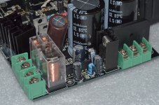
I remove the diodes for the digital power supply and try external power to lower background noise. It is the same. I add extra power caps. It is the same. I try through an RC filter, 5W 30R and 1800uF. Sound is better but background noise the same. I try other ground connections and wire but noise is the same.
The sound is better so I fit the RC into ua7808 regulator with heatsink as pre-regulator for the LT1086, with extra caps. I measure the temperatures. 30R is +30, 7808 heatsink is +28, Lm4766 is +32, LT1086-5 is +32, Lt1086-3.7 is +24. All +room temperature in free air. Power source is from 2 1A diodes. These are used by 7812 for the speaker protection. They come from 15-0-15 toroid input.
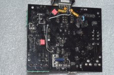
Finally, I fit the Epson SAW 50Mhz. I lift pin13 and solder direct to pin. Power is from 3.3V at CS8421, through ferrite and with 100nF bypass. Sound is more clear and more definition. Next I must remove 33R on mclk trace and pull pin 10 on CS8421 high through 47K to turn off mclk output. But now, I enjoy listening.
I think I cannot fix the noise. It is a shame but now the sound is better than i hope to get, so now it is finished project.... maybe...
I remove the diodes for the digital power supply and try external power to lower background noise. It is the same. I add extra power caps. It is the same. I try through an RC filter, 5W 30R and 1800uF. Sound is better but background noise the same. I try other ground connections and wire but noise is the same.
The sound is better so I fit the RC into ua7808 regulator with heatsink as pre-regulator for the LT1086, with extra caps. I measure the temperatures. 30R is +30, 7808 heatsink is +28, Lm4766 is +32, LT1086-5 is +32, Lt1086-3.7 is +24. All +room temperature in free air. Power source is from 2 1A diodes. These are used by 7812 for the speaker protection. They come from 15-0-15 toroid input.
Finally, I fit the Epson SAW 50Mhz. I lift pin13 and solder direct to pin. Power is from 3.3V at CS8421, through ferrite and with 100nF bypass. Sound is more clear and more definition. Next I must remove 33R on mclk trace and pull pin 10 on CS8421 high through 47K to turn off mclk output. But now, I enjoy listening.
I think I cannot fix the noise. It is a shame but now the sound is better than i hope to get, so now it is finished project.... maybe...
Attachments
Help needed with assembled ES9023 + LM4766 DAC AMP KIT
Hi, I bought this kit as well, and as I am not much of an electronics genius, I bought it fully assembled. Recently I connected a power supply and tested the unit with my brother who is quite knowledgeable. Unfortunately we immediately detected high temperatures near the diodes and we measured wrong currents (i.e. there was a current leakage).
My brother at first thought that one or more diodes had been connected in the wrong direction, but this seems to be OK.
To solve this problem we would need a wiring diagram. Does anyone have that? Does anyone know which things we should check first in order to repair this unit?
Thanks!
- Status
- Not open for further replies.
- Home
- Source & Line
- Digital Line Level
- ES9023 + LM4766 DAC AMP KIT