Re the wonders of a 'giant Cornu spiral... [with] lots of output up into 500Hz':
Output above about 300Hz from a back load = chronic group delay which is very audible for most people. Assuming, for e.g., a 6ft flare path length, then working on average SoS of 1.13ft / ms you've got a delay of 5.3ms up in the 500Hz BW: well above the 3.2ms audibility threshold for that frequency established by Blauert and Laws. A lower acoustic XO is needed, but without some help from the amp, Eq or whatever, the driver will need a short front horn to fill in the region between its mass corner and the practical upper corner frequency of the horn. I wouldn't advise taking any back load much beyond ~300Hz.
Output above about 300Hz from a back load = chronic group delay which is very audible for most people. Assuming, for e.g., a 6ft flare path length, then working on average SoS of 1.13ft / ms you've got a delay of 5.3ms up in the 500Hz BW: well above the 3.2ms audibility threshold for that frequency established by Blauert and Laws. A lower acoustic XO is needed, but without some help from the amp, Eq or whatever, the driver will need a short front horn to fill in the region between its mass corner and the practical upper corner frequency of the horn. I wouldn't advise taking any back load much beyond ~300Hz.
Sorry !
Sorry to interrupt you gentlemen") , but can someone tell me if I'm wrong with my results (using the spreadsheet from Zillasspeak) to design a BIB (using the datas from the AN webpage?
, but can someone tell me if I'm wrong with my results (using the spreadsheet from Zillasspeak) to design a BIB (using the datas from the AN webpage?
The spec. :
Driver : Audio Nirvana Super 8 Cast Frame
sensit. : 97.3 db
equivalent diaghram radius : 88 mm
equivalent mass : 10.023
magnet weight : 1400 g
net weight : 3690 g
Fs : 44.63
Re : 7.2
Mms : 11.748 g
BL : 11.84 TM
Qts : 0.162
Qms : 3.836
Qes : 0.169
Vas : 66.495 ltre
Xmax : 1.0 mm
no : 3.379 %
My results :
Line length : 150,85
Zdriver : 32,73
Sm-terminus area : 110,60
Depth (internal) : 12,51
Width (int.) 8,84
Nominal Height- L/2 : 75,42
Thanks again !
Sorry to interrupt you gentlemen
, but can someone tell me if I'm wrong with my results (using the spreadsheet from Zillasspeak) to design a BIB (using the datas from the AN webpage?The spec. :
Driver : Audio Nirvana Super 8 Cast Frame
sensit. : 97.3 db
equivalent diaghram radius : 88 mm
equivalent mass : 10.023
magnet weight : 1400 g
net weight : 3690 g
Fs : 44.63
Re : 7.2
Mms : 11.748 g
BL : 11.84 TM
Qts : 0.162
Qms : 3.836
Qes : 0.169
Vas : 66.495 ltre
Xmax : 1.0 mm
no : 3.379 %
My results :
Line length : 150,85
Zdriver : 32,73
Sm-terminus area : 110,60
Depth (internal) : 12,51
Width (int.) 8,84
Nominal Height- L/2 : 75,42
Thanks again !
All that does is indicate that the MArk Audio drivers have T/S curves that are closer to horizontal. Hae a look at these measurements of the same pair of FE127eN drivers by Mark & myself (and the factory's for reference (of stock drivers))
dave
That was the picture I was thinking of. I was wrongly remembering the results being closer than that!
If the factory specs are 'in doubt' which do you use to design? My measurements or the factory set?
sorry to OP for clogging up his thread.
That was the picture I was thinking of. I was wrongly remembering the results being closer than that!
If the factory specs are 'in doubt' which do you use to design? My measurements or the factory set?
sorry to OP for clogging up his thread.
No problem ! I was kidding. I will eventually ask one of my friend to measure the spec. of my drivers, but till then it helps me to have your opinion. I can figure more easily how I will do it and if the ceiling of my appartement are high anough !
..........but my amp is not very powerful, it's a SET tube 45 type 1,72 w.
For best power transfer with a SET amp requires the speaker be tuned to Fs, so to sim a BIB with the calculator requires inputting 2xFs and of course true Fs ideally should be known for each driver. Also, the amp's output impedance needs to be added as series resistance to calculate the driver's effective Qts.
Note that based on the published specs for Sd [~243.849 cm^2], Mms, BL, Fs, then Vas = ~91.785 L.
If there's no measurements, then use a ~0.4 Qts and if the amp's output impedance isn't high enough [DF = ~1], then some form of additional series resistance may be required to flatten out the speakers in room response.
GM
If the factory specs are 'in doubt' which do you use to design? My measurements or the factory set?
I always start with the factory numbers.
dave
Indeed. The BIB is a simple tapped corner horn. If it expands toward the terminus, some form of 1/2 wave resonant behaviour is present, ergo, it's a horn. As it happens, GM informed me some years ago that originally 'TQWT' was used in the opposite sense of how it is often employed these days, i.e. it was a pipe that narrowed toward the terminus. Although I suspect he & I are the only people here who continue to use that definition.
Last edited:
ok, I dont want to argue... but.
In english almost all pipes with increasing cross sections are called horns (tapped, tqwt, bib, etc) and that is somewhat confusing.
But classics horn works like acoustice transformer and resonances are negative drawbacks due to decreased size. TQWP - works based on principe of broadband resonator waveguide. They are far relatives, but not twins)
Nevertheless its not so important. What I suppose is more important for such low Qts driver (and soft surrouns, I think) is effectivity of enclosure bass boost and good damping (to limit excursion). That is why classic BLH with compression chamber and throaght less than Sd should be more suitable, I guess.
Last edited:
Who said a horn has to be impedance matched down to its 1/4 wave cut-off?
If a pipe expands toward the terminus, 1/2 wave resonant behaviour is present. Ergo, it's a horn as far as I'm concerned. It may have a terminus sufficiently large to be impedance matched down to the 1/4 wave cut-off frequency, or it may not. But the 1/2 wave behaviour is still inherently present (note that maximum efficiency for a horn comes at 1/2 wavelength) irrespective of that, ergo they share a common characteristic. I can't see the point of making life harder than it needs to be by introducing multiple new descriptions when 'horn' suffices rather well. Especially when the TQWT[P] term traditionally was used for the exact opposite of how it's often used today.
A tapped horn isn't difficult to understand. The driver is tapped into the expansion at x distance from the throat. No big deal there.
The BIB has no throat area at all as it happens (well, actually it does, acoustically, through compression effects, but it's extremely small)
The room is the compression chamber for a back-loaded horn (with less than a handful of reactance-annulled exceptions: count those on the fingers of one hand, with fingers left over).
Last edited:
I think we should let function not form follow the definitions. A classical "bass reflex box" with straight tube as port, can be called a DC horn as the flare of the opening is has a flare rate of 0 Hz.
If we add a flare of 30 Hz to that port and extend it 10 meters it will work as a horn, cutting it down to 1 m it is not much of a 30 Hz horn but will have some pipe resonance at 72-100 Hz. Shortening the horn to 0.1 m we are back at a bass reflex with a minute flare of the port. The fact that you can apply the X equation on design Y does not need to prove that the Y is mainly a X speaker.
The IMF TLS is an inverted parabolic horn but the low frequency cut of does not have the same interaction with mouth area as a Klipsch Corner Horn.
Ok, I think I'll try the BIB.
We expect the photos on the forum !
Claude
Sorry to interrupt you gentlemen
The spec. :
Driver : Audio Nirvana Super 8 Cast Frame
sensit. : 97.3 db
equivalent diaghram radius : 88 mm
equivalent mass : 10.023
magnet weight : 1400 g
net weight : 3690 g
Fs : 44.63
Re : 7.2
Mms : 11.748 g
BL : 11.84 TM
Qts : 0.162
Qms : 3.836
Qes : 0.169
Vas : 66.495 ltre
Xmax : 1.0 mm
no : 3.379 %
My results :
Line length : 150,85
Zdriver : 32,73
Sm-terminus area : 110,60
Depth (internal) : 12,51
Width (int.) 8,84
Nominal Height- L/2 : 75,42
Thanks again !
are the dimensions in Inches? I can use the MJK software to simulate it for you if you wish, seeing as i've offered nothing else of use.
are the dimensions in Inches? I can use the MJK software to simulate it for you if you wish, seeing as i've offered nothing else of use.
Thanks for your reply ! Yes my result are in inches, but I can also give you them in cm.
spartiate1952
Hello,
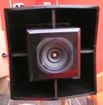
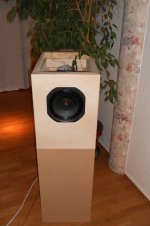
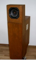
look my HP,
a few satellites and the doublehorns
SAXOPHON, RDH20, POSAUNE XL,
measurements,
compair the RDH20 measurements (2) with the speaker of the Year 2012
rdhmess
Voxativ Ampeggio loudspeaker Measurements | Stereophile.com
Hello,
look my HP,
a few satellites and the doublehorns
SAXOPHON, RDH20, POSAUNE XL,
measurements,
compair the RDH20 measurements (2) with the speaker of the Year 2012
rdhmess
Voxativ Ampeggio loudspeaker Measurements | Stereophile.com
Attachments
- Status
- This old topic is closed. If you want to reopen this topic, contact a moderator using the "Report Post" button.
- Home
- Loudspeakers
- Full Range
- Enclosure for very low QTS ?