As far as I know, the guy said put it in a closed box and use it.infinia said:See what design the other guy had in mind.
My friend can see I've done more for him than that guy on the phone did.Hopefully you'll get all the credit when all your work pays off")
Kudos to all here that have helped me to do that.
Could work ok but may have to tweek the notch a bit.
I think the LT circuit would be your cup-o-tea.
IMO The best EQ for this is the LT circuit. Rod Elliot has a project of the LT on his web site.
As long as I can trim the hump, I'm half way there. Absolute f3 limits are not crucial.
Phase/delay will still be a problem, not sure whether it will be too bad. I guess the LT would clean that up. Is it just a matter of putting current slope/target slope into the spreadsheet and getting circuit values out?
infinia said:
A Sealed system (closed box) from Sreten's earlier advise is definitely NOT advisable for higher Qts (> 0.7).
Hmmm...... a contradictive statement that is incorrect.
A higher Q 2nd order alignment combined with a 1st order roll-off
as suggested by E-side gives you a half reasonable 3rd order
alignment that has similar phase and group delay characteristics
to standard 4th order vented alignments, (perhaps better).
Aperiodic vents waste some of the excursion capability. As pointed
out by E-side the 3rd order alignment has some power handling
advantages as it effectively rejects low bass and the excursion
required. Could be a very good choice if the driver has low xmax.
/sreten.Indm
A good explanation of what the LT equalizer is doing can be read Rods site. Link http://sound.westhost.com/linkwitz-transform.htm
Most people use this technique for getting LF extension in a smallish box at the expense of amplifier and driver power. Should you choose to go this way, you would be using it mainly to control the severe peak.
Download the spreadsheets and use the vaues estimated from a box calculator. I would advise using low gains, just to control the peaking (gains around 6-8 dB). If you choose to build it, hold off on final filter values untill you measure the driver in it's box.
infinia said:
Most people use this technique for getting LF extension in a smallish box at the expense of amplifier and driver power.
SPL and power(handling) are usually very important factors for PA speakers and amplifiers. To compensate a 3dB waste of power requires a bigger amp, and a bigger wallet. Especially if cost is an issue, and when cheaper, less sensitive speakers are used, a LT isn't a good option in my point of view.
Also, PA speakers often don't go any lower than 40 or 50 Hz, everything below these frequencies usually isn't worth the required extra Watts.
e-side said:
SPL and power(handling) are usually very important factors for PA speakers and amplifiers. To compensate a 3dB waste of power requires a bigger amp, and a bigger wallet. Especially if cost is an issue, and when cheaper, less sensitive speakers are used, a LT isn't a good option in my point of view.
Also, PA speakers often don't go any lower than 40 or 50 Hz, everything below these frequencies usually isn't worth the required extra Watts.
What you say is true, If you push the LF extension.
Here the LT equalizer is being used for Q correction and should not be a bad trade off if the LF extension is kept within reason. That's why I warn against making the gain any higher than necessary. Not too much different than using a simple HPF if the break points are chosen judiciously.
infinia said:Sreten
Now you're confusing your passive solution of a simple closed box suggested in your first post with eside's active filter solution he suggested later on. I agree with eside solution, it has some merit similar to what the LT does but
Hi,
I'm not confusing anything. The principle of my original post (if
you read it all) is the same as E-side's just somewhat simpler.
/sreten.infinia said:Sreten
Now you're confusing your passive solution of a simple closed box
suggested in your first post with eside's active filter solution he
suggested later on .........
Hi,
I'm not confusing anything. The principle of E-sides post is the
same as my original post (it illustrates it, as he's modelled it)
but the my suggested implementation is the simplest (EQ).
/sreten.Indm!
An easy passive cure to lower driver Qts / Qms:
Background from:
/
Small : Chapter 6. DRIVER DAMPING AND VARIATIONS OF THE CLOSED-BOX SYSTEM
6.2. Acoustic Damping of the Driver :
The simplest way to correct a high value of QTS is to apply acoustic damping directly to the driver using a shroud of acoustically resistive material as described in [G1] or [N3]. This effectively adds resistance in series with RAS and leads to a value of QM ( Section 1.5.4 ) lower than QMS. By suitable choice of the kind and amount of damping material, almost any desired value of QT can be obtained regardless of the value of QES or QE. The parameter measurement methods of Section 9.2 may be used to determine experimentally the amount of material needed to meet a particular requirement. Care must be taken that the material remains stationary.
/
My suggestion: Change driver Qms by fitting a 3-4 inch thick cylinder of glass fiber or mineral wool, (1.25 -1.5 lb/ft3 glued Liquid Nail type) to the rear side of the baffle adjusted to completely covering the rear outlets of the driver.
The fibres must be oriented perpendicular to the baffle, also letting air to be passed through without any fibre moving.
Fibre-cylinder inner diameter is equal to the magnet diameter and the latter has also some glue on the surface for fastening the wool securing unwanted fibre movement.
The length of the cylinder is about equal or slightly longer than the formed cylinder outer diameter.
Carefully done this should push Qm down to under Qm=1, resulting in a better driver mechanical system behaviour.
Midband efficiency will drop down a bit, maybe a 1 dB or so and the air column formed in the fibre will add mass causing fs to drop slightly.
Bjorno
Infinia
---pwr amp should be configured as a current source (AB w collector outputs). Small resistor samples the current at output return then applies neg feedback with trickey compensation network in feedback loop. A stability analysis would be required. IMO this technique needs a special dedicated pwr amp for woofer only.---
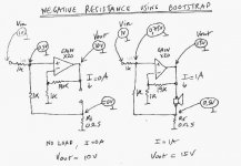
Negative resistance can be obtained from standard voltage amplifiers and do not use current source. I have some experience with a bootstrap circuit which was probably known before negative feedback in tube amplifiers. At these times, it was used to get a low output impedance.
Here is my circuit having a negative outpout resistance of -5 Ohm. When experimenting, a polyswitch in series with the speaker makes a good protection.
---pwr amp should be configured as a current source (AB w collector outputs). Small resistor samples the current at output return then applies neg feedback with trickey compensation network in feedback loop. A stability analysis would be required. IMO this technique needs a special dedicated pwr amp for woofer only.---
Negative resistance can be obtained from standard voltage amplifiers and do not use current source. I have some experience with a bootstrap circuit which was probably known before negative feedback in tube amplifiers. At these times, it was used to get a low output impedance.
Here is my circuit having a negative outpout resistance of -5 Ohm. When experimenting, a polyswitch in series with the speaker makes a good protection.
Attachments
Mostly from the 70-80's though.
Yes, It was popular to build amps with negative output impedance 70 - 85 using these articles.
Still have a very good bass amp I made in 1984 for adjusting FR bandwidth and Qts.
Take a look at the schematic:
B
Attachments
bjorno said:
Yes, It was popular to build amps with negative output impedance 70 - 85 using these articles.
Still have a very good bass amp I made in 1984 for adjusting FR bandwidth and Qts.
Take a look at the schematic:
B
Hi bjorno
Thanks for posting your schematic. I like pictures instead of words. I see the output is a current source. It's a transconductance amp with multiple feedback points. In essance provides the conjugate impedance seen by the woofer.
How do you like it still?
Hi Infinia,
I've been using that prototyped amp for over 20 years with great success and build more than 10 for friends.
It’s still very useful to prototype different bas cabinets with different drivers mostly below 200 Hz due to the driver Le, but when using Scan-Speak low inductance drivers much higher upper corner is achievable.
Today though, I have to change the burned on/off switch that is worn out from extensive use.
B
bjorno said:Hi Infinia,
I've been using that prototyped amp for over 20 years with great success and build more than 10 for friends.
B
Hi bjorno
Must be around 70 Watt/8ohm or about. Can you run isobaric or push pull woofers?
Thanks a lot, Bjorno, for your schematics, I collect everything I can get about negative impedance and Stahl schemes.
Just as with bridge velocity motion feedback, the problem with the Stahl scheme is Le which is not constant with frequency and within the voice coil position in the gap. Stahl and yours schematics solves this last aspect by using a push-pull configuration of the drivers.
I am happy you confirm what I thought : the Scanspeak driver wiht reduced Le were good candidates for this application.
Infinia
The current sensing circuit is not used to make a transimpedance amplifier (voltage in, current out) but to determine an amplifier with a precise output impedance.
Stahl's configuration uses are two feedback loops :
- the first one is a positive feedback loop which completely nullifies the Re of the driver. Left alone, the system would be absolutely instable.
- the second loop imposes a particular impedance to the output of the power amplifier and controls the resistance which will determine the Qe of the whole and will assure the stability.
For the driver which is the subject of this thread, I just suggest to use a little of negative resistance to get a more decent Qt by lowering the Qe.
- Status
- This old topic is closed. If you want to reopen this topic, contact a moderator using the "Report Post" button.
- Home
- Loudspeakers
- Multi-Way
- Enclosure for high Q driver