Wiki one step
Mongo prodded me in the ribs and gave this to me. He said he recognizes things on a basic level...a "close to his roots" kinda guy. I don't know where he gets it. I was going to blow him off, but he kept that thumb in my ribs...and he's bigger than me. To wit:
A system refined by and for the process of survival is the means through which we evaluate sound. Those sounds which the correlator determines are a threat may provoke an involuntary response (fight or flight?). In the absence of threat we may choose to continue perceiving the sound, possibly leading to value judgments about it.
The development of the threat assessment system did not include electronically produced sounds. Electronic sounds include aberrant attributes which our hardwiring makes no allowance for. We are genetically unfamiliar with those attributes. They exist across several spectra. The magnitude of those attributes is directly related to the degree to which equipment producing them is aberrant. Still, part of that spectrum lies below the conscious decision level. Long term exposure to aberrant attributes will raise them from the subconscious level to a conscious level. Lowering and maintenance of those aberrant attributes to subconscous levels and lower lessens the likliehood of distraction from the listening process, for the sake of listening.
Seems to me there's more to it than that. It's all he has so far
EnABL WIKI STEP two,
The threat assessment system is based upon biological timing and distance expectation relationships. When these "speed" and movement and duration limits are breached, the correlator assumes a threat and begins the process of assessment.
An event that exceeds the expected biological unfolding of events is a "red flag" issue. Something is moving faster, or changing state faster, than the 3 million years of mammalian and precursor learning and surviving to mate, has provided for.
In an audio system a response "speed" that exceeds this "intelligibility" envelope is an irritant but not a red flag event. The irritant can be adjusted to, but it remains an irritant. When the irritation is relieved, after a period of adjustment long enough for the correlator to have ceased consciousness notification activities, a "relief" is felt, but no particular event is addressed. The relief might also bring with it other disturbing insults, but they are not immediately acknowledged and even when later acknowledged may be ignored due to their association, at a level not usually addressed by the consciousness, with the relief of that prior irritant.
So, there is a speed limit to a reproduction chain, that if exceeded, must be consciously accepted and repeatedly reinforced as an acceptable event.
A clear example of this came as we were developing a series of guitar amplifier output transformers. A typical guitar amp is an amazingly responsive device and is part of a musical instrument.
As a good friend of mine, the acknowledged premier guitar amp designer guru on this planet, has pointed out, an output transformer is 90% of what is wrong with any given amplifier but only 70 % of what is right. Turns out that one of the "wrongs" an OPT can bring, is a response that allows the amplifier to exceed the "speed" that a musician is willing to "play" with.
As we developed these things, applying our technology for removing zero crossing distortion causing reminance from the core, we found we had to use a poorer grade of core so that the permittivity of the core did not allow a transient signal to rise "too fast". For most of our OPT's for guitar amps, we now use M50 core material. The speed with which a magnetic plane is formed, in the core window of that material, is just perfect for the usage.
We then had to explore coil permittivity and since we had such a malleable, low phase distortion, core assembly, we discovered that a dielectric circuit could be formed, from a specific application of materials to specific locations. One that would allow an amplitude based time slew, a frequency and phase based tone slew and when properly matched to the core permittivity, allowed an incredibly responsive OPT, but, it did not exceed the "speed" limit that musicians found to be natural and desirable. These material choices and their location specific usage overturn a long accepted paradigm in magnetic design. Lumped parameter capacitance has been picked apart and choices over how to reinforce "working capacitance" and limit the effect of distributed capacitance are now available and predictable.
And yes, we did explore faster collections of core and coil materials. These were the ones that lead us to our Audio Reproduction transformers, that many people say are the best in the world. But, they still are not made from the materials with the "best" objective performance, as judged by an impartial quantitative analysis, even though that is accepted electrical and magnetic engineering dogma.
The result of these investigations reinforced the notion that a speaker system that reproduces sound characters that equal the expected "speed" of events, that a correlator is least likely to flag as unusual, actually embodies what is always referred to as "better" or "best" sounding in a qualitative sense.
The EnABL process is just such a device. It slows down the effective speed with which a sonic event is reproduced by materials, whose propagation rates for transverse waves, grossly exceed the speed of compression wave propagation in air and allows materials that are not by themselves, up to an acceptable rate, to fall within that acceptable "speed" range. That it also eliminates reflections on the radiating surface only serves to further reduce correlator irritations and allows it to search ever deeper into the sonic events for threats.
This is why, once you get your hands on a set of EnABL'ed drivers everything else just sounds irritating, so, be warned. The things are just immensely satisfying, on a level you may not even be aware of, until something added to the music reproduction system gets flagged as a threat.
Bud
WT,
Don't ignore the center dome / bottom of the cone, treatment. Back a few pages is a picture of a Yamaha two way treated by Ultrakaz. The center dome on the woofer is done almost perfectly. You can move the rows of blocks on the dome down so that the bottom row is in the valley of the join between cone and dome. Then, instead of a double row on the cone, move that pattern set down and use the bottom row for the dome, in the valley, as your bottom row for the cone too. This actually works better than two separate sets of rows as Ultrakaz applied, before I could get to him to suggest this row reduction scheme.
Also note how few dots are actually on the center of the dome, rows. This few in number will just turn that dome center off and eliminate the beaming that domes often have. Then you cut the end off of a round toothpick and dip the barrel end into PVA / Elmer's or whomever supplies white wood glue in Thailand. Then place this dot right in the center of that red circle, in the center of Ultrakaz's dome, on your speakers. After it has dried, paint over it, very lightly, with the Micro Gloss. This silly dot will control the dispersion pattern for the whole cone and all frequencies above the perfect piston frequency of the cone..
Bud
Bud,
I have a question about EnABL pattern on a small wide range driver I have. The driver is the HiVi B3S. It is a 3" aluminum cone with no center cap. Looks like the inside of a round spoon. So would you suggest;
EnABL pattern at outside of cone + center dot
or
EnABL pattern at outside of cone + EnABL pattern at voice coil + center dot
or
Something else?
Thank you.
boone
Bud,
I plan on putting into service a pair of Altec 511b horns in the future. In addition to horn damping, I am interested in trying your EnABL process. Are you familiar with the horn and if so, would you offer any suggestions?
Thanks,
Marc
Edit: I just scrolled back and I see a lot of requests for specific suggestions! If you don't find the time to reply I certainly understand!
Boone,
Door number two. Use a three ring pattern with the center ring as close to right over the voice coil as you can manage. Again, absolute precision is not needed. Since all of the materials come off with alcohol you can experiment for yourself, but this is how I would treat it. I would also apply the Gloss Coat just over the pattern and wait a day and listen. You are listening for frequency areas that sound "covered" or "stopped up". A female singer whose nasal harmonics don't express properly, as if she had a snotty nose or cello's that don't have a resiny sort of color all the way up their scale. Small, subtle things, but this should be the level you are working on.
You may end up upgrading the rest of your system in this process so try not to become absorbed in the process. Also metal drivers are problematical, there always seems to be a resonance that just will not go away. This is not the case for all drivers, but, be aware....
Don't hesitate to report back regardless of what you find, or for requests for help in solving a problem you uncover. You may also end up treating the back side.
Ed,
How brave are you? If you are going to remove the fascia plate to get at the front, contemplate removing the dome, to get at the back and treat both sides of the dome.... just a thought, and you should approach with caution, but most dome tweeters are made so you can replace the dome. Then, some day when you are feeling good, buy a pair of silk dome tweeters of the sort that Audax made in the 80's and 90's. Treat these on both sides and compare them to the metal domes done the same way.
limono,
I have treated a number of cartridge bodies. For some reason the Techniques cartridges worked the best. I treat the area around the exit of the needle shaft from the pivot bearing. Use a very fine tipped technical pen and a 50% mix of the flat clear acrylic paint and clean water. It takes a while for this stuff to get through the pen stem so just keep shaking the thing until it come out.
I also treat the area around the cartridge body where the mounting surface and head contact occur. A ring around the body, about 1mm down from the contact point should do. You can also put rings on either end of your arm. However, no guarantees on how much difference any of it will make.
Based upon how sensitive the the Lowthers are, which are set to ship Monday, you will be able to hear ANY difference that is accomplished, for better or worse.
mpmarino,
I have very limited experience with horns. Every one of them I have treated ceased to have the horn sound coloration that some had more of than others. The resultant sound was a bit more detailed or a lot more detailed, depending upon the treatment level and the design sophistication of the compression driver assembly.
The other important result is the increase in intensity. The intensity is solid right across the angle of the horn, so the "sweet spot" increases to that included angle and directly on axis looses it's extra emphasis. This was true with rectangular, oval and conic horns. Also true of what drove them, with even piezo electric horns becoming crystal clear. I still don't care for their sonic qualities but they are quite clear about them, after treatment.
Look at the white paper here.
http://www.positive-feedback.com/Issue21/standingwaves.htm
About two thirds of the way through, a patent drawing of a typical horn treatment is shown. This will give you an idea of how to go about this process.
If you are interested in greater intensity and dispersion I do recommend trying it out, since you can remove it if you are not impressed.
Bud
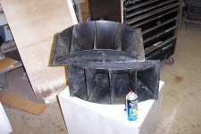
Thank you for your reply Bud. Yes, I had seen the paper which is what lead me to the question. I should have been more detailed in my question. Attached is a pic of my beater 511Bs. You can see that they are divided. These divisions do not go as far as the throat - they are only about 1/3 the way down from the front of the mouth creating cells - almost. Should I treat each 'semi-cell' as an individual entity or should I ignore the dividers and just treat the mouth ?
Also, I will be applying a new finish. I was going to use just a flat black BUT I am wondering if maybe a glossier surface may improve the effect of the treatment?
Thank You
Also, I will be applying a new finish. I was going to use just a flat black BUT I am wondering if maybe a glossier surface may improve the effect of the treatment?
Thank You
Attachments
mpmarino,
Go ahead and finish your horn to taste, allow it to cure for a while and listen to it until you are familiar with how it performs at low levels, with occasional excursions, of course.
Measure the entire flare end size and, using polar coordinate paper, derive a general length per block. This is the size to use for a single set of block rings at the flare aperture. To treat each cell you take a single cell dimension and convert it into a round circumference, find the radius or diameter and find the appropriate ring on the Polar paper and, using the radians divide a 10 degree block up into 4 degree, 2 degree, 4 degree of arc sections and then measure the length of each 4 degree block arc. This is the general block length you will need to use to make a straight line pattern, whose block size suits the edge being treated. Use this same activity to derive blocks for a full flare end treatment also. Regardless of the calculated block length I would not use an individual block sector, of 4 degrees, larger than an inch in length, no matter where you might be putting it.
Applying rows of blocks to every cell will provide greater impedance to the horn boundary layer and you will likely have to use the Micro Scale, Gloss Coat acrylic paint to increase the thickness of the boundary layer. You will get the greatest amount of control with this scheme, but, you may not need that much control over the energy moving down the horn attached to the boundary layer. In addition you really do want to treat the horn throat as well, right where it attaches to the compression driver. Definitely coat the pattern rows at the throat with Gloss and maybe the blocks at the flare end if it is a single set for the entire flare end. If you go for the cell patterns you will have to coat those and may have to coat the entire inside of the horn, at which point you might as well take care of the cell entry edges also. You could get quite extremely crazed here and with only a modest benefit over the pattern applied to the whole flare end.
The hardest task here is not to do too much, best to do just enough and leave it at that. Then, as you improve the rest of your system using these newfound tools, you might do more to top it off. Just take it slow and step by step is my advice, but definitely treat both ends of the horn terminus's.
Bud
soongsc said:It's amazing nobody is posting new measurements here.
Too busy listening?

After a series of interesting tests, too much to post, I'm summarizing some findings and some thoughs below.
1. Patterns like the EnABL will create a phase lead in the response. This is an indication that the boundary layer separation does indeed occur. The outer row seems to make the phase lead start around 8KHz, the inner row seems to make the phase lead start much lower.
2. There is no significant change in frequency response (amplitude) below 10KHz due to the pattern.
3. Influence in frequency response above 10KHz may be due to the weight of the pattern themselves, for some small drivers I could gradually change the weight of the pattern (to the second digit in grams) such that the the frequency response between 15KHz~23KHz can be tuned changing weight to each row in the pattern while no siginificant further change in phase takes place.
4. These test were conducted on metal coned drivers. I believe that for paper drivers, the additional coating effects the frequency response more than the weight will.
I will take time to sort out the test data if others also post their measurements.
Hope this information is useful.
What about audible differences?
1. Cleaner sound as indicated by the CSD.
2. Better image focus.
3. Increased stage depth.
4. Reduced sonic signature from the cone.
This is about the best I know how to describe it. Each driver needs to be individually tuned for optimum results, otherwise it may sound different, but not more correct. This means you cannot just blindly apply the pattern. Measurement and understanding of the data is a must.
soongsc,
Thank you for the test data summaries.
When you speak of "tunning" for a specific driver, are you speaking of matching a change in block size to a change in swept emitter surface, as a controlled parameter?
I am quite familiar with the tuning portion, but I have always relied upon discreet use of the gloss coat to obtain audibly, spectrally flat wave emission. To me this means that at given distances from the emitter surface, the spectral balance remains constant across the radiating area described by the drivers physical angle of incidence. I strive for this characteristic in the hand done units I process.
Since a Wiki definition is being constructed would you donate specific CSD pictures? I sort of doubt that there is anyone else that has both the equipment and skill / knowledge / interest to duplicate your results and I think your efforts should get further recognition.
Most folks simply do not realize there is a problem and thus find it hard to become interested in finding a solution, even though the categories of impact that you enumerate, address almost all loudspeaker deficiencies.
I have to admit that I have no knowledge reference for that description, what it indicates about the construction of a coherent and timely compression wave nor how to maximize this characteristic. Could you please elaborate?
I am quite interested in your frequency Vs control pattern comments. To my ear the addition of the inner ring to a cone speaker, when it is sitting on a horizontal surface in front of me with an external ring already applied, has the effect of "flattening" in perceived space, the projected musical recreation.
If you imagine the cone final edge as a virtual horizontal stage, with performers arising upon it, a surprisingly easy thing to do, then the inner ring "flattened" that stage floor, across the cone opening. Prior to application, that stage is not well defined and has some odd stretched portrayals. Is this phenomena in accordance with your phase lead descriptions?
I hope your investigations have lead you to some personnel skill and knowledge that will further your goals. I realize that this is an academic pursuit for you, at the moment, but I do hope you look into some larger investigations, not necessarily related to audio, with the understanding you have acquired. Are you going to investigate other "broken patterns" in a comparative sense?
Bud
Thank you for the test data summaries.
When you speak of "tunning" for a specific driver, are you speaking of matching a change in block size to a change in swept emitter surface, as a controlled parameter?
I am quite familiar with the tuning portion, but I have always relied upon discreet use of the gloss coat to obtain audibly, spectrally flat wave emission. To me this means that at given distances from the emitter surface, the spectral balance remains constant across the radiating area described by the drivers physical angle of incidence. I strive for this characteristic in the hand done units I process.
Since a Wiki definition is being constructed would you donate specific CSD pictures? I sort of doubt that there is anyone else that has both the equipment and skill / knowledge / interest to duplicate your results and I think your efforts should get further recognition.
Most folks simply do not realize there is a problem and thus find it hard to become interested in finding a solution, even though the categories of impact that you enumerate, address almost all loudspeaker deficiencies.
1. Patterns like the EnABL will create a phase lead in the response. This is an indication that the boundary layer separation does indeed occur. The outer row seems to make the phase lead start around 8KHz, the inner row seems to make the phase lead start much lower.
I have to admit that I have no knowledge reference for that description, what it indicates about the construction of a coherent and timely compression wave nor how to maximize this characteristic. Could you please elaborate?
I am quite interested in your frequency Vs control pattern comments. To my ear the addition of the inner ring to a cone speaker, when it is sitting on a horizontal surface in front of me with an external ring already applied, has the effect of "flattening" in perceived space, the projected musical recreation.
If you imagine the cone final edge as a virtual horizontal stage, with performers arising upon it, a surprisingly easy thing to do, then the inner ring "flattened" that stage floor, across the cone opening. Prior to application, that stage is not well defined and has some odd stretched portrayals. Is this phenomena in accordance with your phase lead descriptions?
I hope your investigations have lead you to some personnel skill and knowledge that will further your goals. I realize that this is an academic pursuit for you, at the moment, but I do hope you look into some larger investigations, not necessarily related to audio, with the understanding you have acquired. Are you going to investigate other "broken patterns" in a comparative sense?
Bud
- Status
- Not open for further replies.
- Home
- Loudspeakers
- Multi-Way
- EnABL Processes