There are some mention of the Juli@ soundcard in this thread have anybody done any modifications to it?
Or have the schematics or traced some of the analog sections?
I though I would start looking a little closer on how its implemented tomorrow, and it would be nice to have a headstart.
I have noticed there is a pads for a 5x7mm oscillator right under the 22.579Mhz crystal with some luck that turns out to be a very convenient way to improve the x44.1K rates.
Thanks -- as you can tell, i am unlikely to redo from scratch what others already did without details... too time consuming. Too many projects and trying to sell a house as well. So, i'll get back to this mod when i have more time. meanwhile, i'll try the eMu-0404 that i did a mod and use ARTA with it. I want to see if either e-Mu model is better than the QA400 in accuracy at low distortion levels.
Thx-RNMarsh
One EMU0204 may not be the same as another. Things do go through revision and the part designators maybe different. I'm too busy to do anything myself right now.
The trouble with the EMUs and other sound cards is there are no schematics for them.
The best that can be done is to trace everything out and document it. This is difficult with SMT and getting values in circuit is a chore.
Good luck.
Indeed but alteast the components are numbered..
To make matters worse the Juli@ PCB is covered in some thick white surface counting making following surface traces almost impossible, even under a microscope. Luckily they are only using 0603 components so most of the resistors values are readily readable.
Anyway I mounted a pair of 0402 47ohms across the ADC inputs to get some sense of the analogue parts influence on the noisefloor, I will try to improve the decoupling and the Vref filtering tomorrow to see what effect that gives.
Attachments
Last edited:
There are some mention of the Juli@ soundcard in this thread have anybody done any modifications to it?
Or have the schematics or traced some of the analog sections?
I though I would start looking a little closer on how its implemented tomorrow, and it would be nice to have a headstart.
I have noticed there is a pads for a 5x7mm oscillator right under the 22.579Mhz crystal with some luck that turns out to be a very convenient way to improve the x44.1K rates.
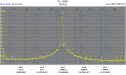
There is a bunch of stuff on the web for the Juli card but its mostly focused on digital playback. The pads for the oscillator on the back I think are misleading. The card as is is pretty free of jitter. I measured less that 20 pS wideband. On a JTest its also very clean It does have other noises. You can see them in the attached plots.
The opamps are a limitation since nothing else uses that footprint. I have not done measurements with the balanced interface.
I would use (and do use) an external capture card connected with SPDIF. You get isolation and can run it 50' away if needed.
Attachments
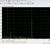
The card as is is pretty free of jitter. I measured less that 20 pS wideband. On a JTest its also very clean It does have other noises. You can see them in the attached plots.
Currently I do not see the real JTest....

The test is based on a 16 Bit source with a LSB toggle, the strong signal is Fs/4 signal (level may -6 dBFS or else) & LSB Toggle at Fs/192.
Then you will see low level & low freq. square wave (with its fourrier compnents) abr. at -96dBFS and a strong signal at fs/4. The fs/4 signal should be zoomed in to get the phase noise or to see symmetric signals (not a periode of the LSB toggle)...
Or visite my home page and naviagte to Support\HpW Tech
my 2 cents on this
Hp
You are right, it isn't a standard Jtest. Its a measurement I made some time ago and I didn't document all the details. Its a measurement of the capture side. The 8 KHz bandwidth comes from the presentation at Stereophile. When I get my shop back up and running I'll redo it.
I'm not sure that a low level signal on top of a main carrier will show anything on a capture system. Is there a better method of verifying jitter on the ADC side? Do you have a JTest file that you can share as a source? I have several but I'm not sure of their freedom from errors.
I'm not sure that a low level signal on top of a main carrier will show anything on a capture system. Is there a better method of verifying jitter on the ADC side? Do you have a JTest file that you can share as a source? I have several but I'm not sure of their freedom from errors.
I'm not sure that a low level signal on top of a main carrier will show anything on a capture system.
16 Bit LSB toggle = a square wave should be clearly visible on a 24 bit DAC & ADC.
Is there a better method of verifying jitter on the ADC side?
The best so far if the source master clock is 100% in think with the ADC, then you do a coherent measurement and any FFT Window may will be not required.
Do you have a JTest file that you can share as a source? I have several but I'm not sure of their freedom from errors.
this is nicely integrated within my wave generator with various D-Jitter alike signals. hp
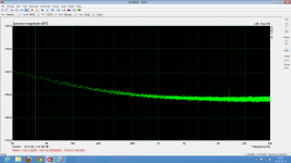
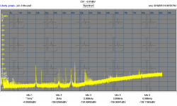
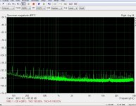
Here is what I get with the following small changes:
Two LT1117 replaced with LT1763 (one of these is 5V analog supply and the other general 3.3V digital)
Addition of 680uF/4V poscaps on the ADC Vref decoupling
100nF//10uF (0603) decoupling around the ADC
Two LT1117 replaced with LT1763 (one of these is 5V analog supply and the other general 3.3V digital)
Addition of 680uF/4V poscaps on the ADC Vref decoupling
100nF//10uF (0603) decoupling around the ADC
Attachments

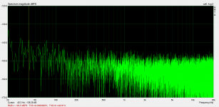
Hi All
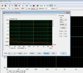
looks like I found a good combination of driver and OS, this is measure the board E-MU 0404 PCI with Win7-32 Bits -SP1. SpectraPlus and RightMark do not accept the board at 96KHz in Win7.
looks like I found a good combination of driver and OS, this is measure the board E-MU 0404 PCI with Win7-32 Bits -SP1. SpectraPlus and RightMark do not accept the board at 96KHz in Win7.
Attachments

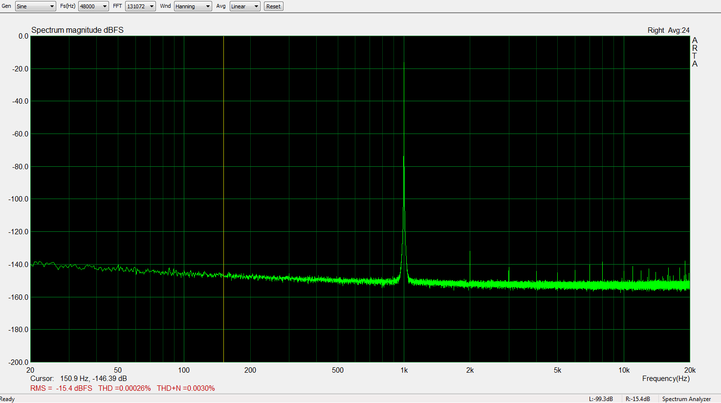
Here is what I get with the following small changes:
Two LT1117 replaced with LT1763 (one of these is 5V analog supply and the other general 3.3V digital)
Addition of 680uF/4V poscaps on the ADC Vref decoupling
100nF//10uF (0603) decoupling around the ADC
This is what I am looking for... any brand that you can get rid of the parasitic freqs and are left with just the noise of the system. Then what you see as harmonics are only those from the device under test (DUT).
Can you send a photo of the the changed parts/location?? Without access to schematics, pictures are the next best thing.
Thx-RNMarsh
Last edited:
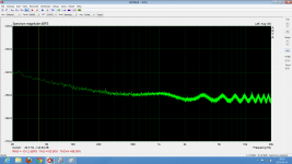
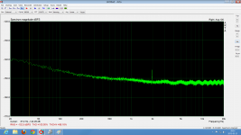
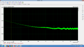
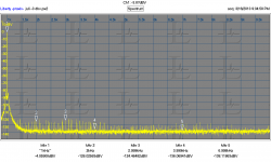
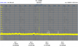
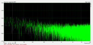
With the input stage bits connected to the ADC I always saw a group of spikes at about -120dbFS wandering a couple of kHz in frequency in a group together, spaced at about 10k 13k 16k that just did not want to go away and just turned into ugly plateaus with averaging.
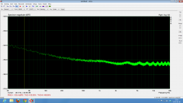
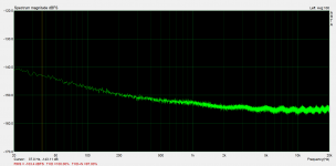
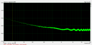
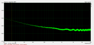
These still remained when i removed the 47R's across the ADC inputs so I did further changes, I suspected supply modulation so I started with replacing the lytics right next to the 7xM09 regs to 100uF/16V oscons and paralleled the local (ceramic) decoupling around the 7xM09 with 10uF/25V 0805 and I also put some impedance between the Juli@'s anlogue circuitry and the PC Power planes so I cut up the pin header supplying the +/-12V to the half of the juli@ PCB with the analog stuff and soldered in a pair of 10uH / 0.5A / 0.75Ohm SMD inductors since that was what I found with a convenient physical size.
No great change.
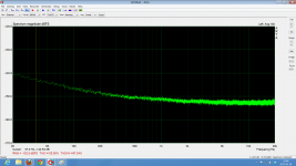
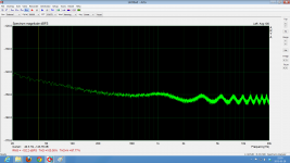
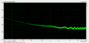
Figured I should also put something in with plenty low impedance at the frequency of interest to bump the PSSR by giving mostly the added R of the inductors something to work against. Since there is easy access to the power planes on the juli@ through the top top side connector. That can be accomplished rather neatly. I just hacked up an experiment board, mounted a pin header and two 10mF/16V Panasonic NGH's
And here is the result:
These still remained when i removed the 47R's across the ADC inputs so I did further changes, I suspected supply modulation so I started with replacing the lytics right next to the 7xM09 regs to 100uF/16V oscons and paralleled the local (ceramic) decoupling around the 7xM09 with 10uF/25V 0805 and I also put some impedance between the Juli@'s anlogue circuitry and the PC Power planes so I cut up the pin header supplying the +/-12V to the half of the juli@ PCB with the analog stuff and soldered in a pair of 10uH / 0.5A / 0.75Ohm SMD inductors since that was what I found with a convenient physical size.
No great change.
Figured I should also put something in with plenty low impedance at the frequency of interest to bump the PSSR by giving mostly the added R of the inductors something to work against. Since there is easy access to the power planes on the juli@ through the top top side connector. That can be accomplished rather neatly. I just hacked up an experiment board, mounted a pin header and two 10mF/16V Panasonic NGH's
And here is the result:
Attachments
-
 1000uf_Additional_deco_96k_R_47R_0AVG.png27.6 KB · Views: 118
 -
 1000uf_Additional_deco_96k_L.png74.8 KB · Views: 111
 -
 1000uf_Additional_deco_88k2_L.png25.4 KB · Views: 127
 -
 1000uf_Additional_deco_96k_R.png25.5 KB · Views: 136
 -
 1000uf_Additional_deco_88k2_R.png26 KB · Views: 428
 -
 1000uf_Additional_deco_96k_L_47R_0AVG.png27.8 KB · Views: 126
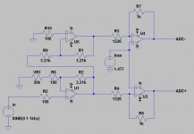
I would try something like this. It will be a bit more work to implement but you maintain a HighZ input and a gain control (up to +30dB) with few drawbacks.
Running it with high gain will increase THD by loading the output of U1. If that is the case you can try changing the 3.21k resistors for something more like 20K, R6 for 620R, and the gain pot should be changed for 100k so the gain can still be adjusted down to near Av=1
If you don't need any gain, omit the volume pot and R6, short R2.
Attachments
Last edited:
I would try something like this. It will be a bit more work to implement but you maintain a HighZ input and a gain control (up to +30dB) with few drawbacks.
Running it with high gain will increase THD by loading the output of U1. If that is the case you can try changing the 3.21k resistors for something more like 20K, R6 for 620R, and the gain pot should be changed for 100k so the gain can still be adjusted down to near Av=1
If you don't need any gain, omit the volume pot and R6, short R2.
Agreed.
It was simpler to wire the other way and it provides a lower source R for lower noise. That's the only reasons.
I left the other channel at a high input impedance variable gain.
I don't see much issue with increased distortion from loading U1 with a 3k resistor.
The op amps EMU used are very good and I wouldn't consider replacing them. They seem to handle the loading well.
If a notch filter is used it really doesn't matter.
Cheers,
Last edited:
I received an 0204 a few weeks ago. Mine had slightly different values than the schematics posted here. In my unit the 3.21k resistors are 3.01k, and the 1.326k are 1.37k - not really going to make any difference, i just thought it was worth noting. The resistors are also numbered differently. The PCB is labeled "Model:EM8741 001004"
I confirmed that one of the differential pairs to the ADC has about double the amplitude when the gain pot is set to minimum.
I implemented the mod i posted above, but changed R6 to 1ohm which gives a theoretical variable gain from 0db to ~70dB. There is a 1.5ohm resistor on the board to limit the gain to ~60dB, but it was just easier (in my opinion) to cut the traces and use a new resistor. I didn't have a 1.5ohm resistor on hand, so i just used a 1ohm. The pot itself is probably going to add a bit of resistance anyway.
Basic method:
-Cut the two traces on the backside of the PCB going from the opamp to the pot.
-Solder a 1ohm resistor from one side of the pot to the AGND test pad on the top side of the PCB.
-Add wire connecting the other side of pot to U5b inverting input.
-Add 3K resistor between U5b output and U5a inverting input.
edit: just realised i did the before measurements wrong, doing new ones now
Last edited:

Agreed.
It was simpler to wire the other way and it provides a lower source R for lower noise. That's the only reasons.
I left the other channel at a high input impedance variable gain.
I don't see much issue with increased distortion from loading U1 with a 3k resistor.
The op amps EMU used are very good and I wouldn't consider replacing them. They seem to handle the loading well.
If a notch filter is used it really doesn't matter.
Cheers,
Just an update.
I found I get better noise performance by keeping the input Z high on the op amp inputs so the non inverting configuration is better. It may require a bit of cutting and routing resistors is a bit more complex but the performance is worth it.
I suspected EMU may have made changes to the board depending on vintage. Pictorials may be a better way show changes than quoting part designator numbers.
Cheers,
- Status
- This old topic is closed. If you want to reopen this topic, contact a moderator using the "Report Post" button.
- Home
- Design & Build
- Equipment & Tools
- EMU0204 mods for FFT measurements