might i suggest a little different circuit for the biascurrent, becous in this situation you will not have any quasy current, or you have to many quasi current, couse of the high current gane in the output circuit it wil be very unstable and inpossible to know what it will do.
Greetz Rudy
Greetz Rudy
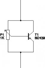
no not the transistors, they are fine, you need to replace the 2 diodes D2, D3 with a little circuit, and make sure when you power the thing on that the middle connection of the potentiometer is conncted to the topside ( in the drawing ofcourse ) so that the transistor ( who must be connected to the same heatsink as the power transistors ) reduces the idle current to zero. Then slowly turn the potmeter around until you find yourself a descent bias value.
Good luck with your amp btw
Greetz Rudy
Good luck with your amp btw
Greetz Rudy
Attachments
DJ,
I have no good news for You MJE15030/031, are not very good instead of MJE340/350. With lower current the MJEs have lower B. They are ideal driver devices, but not ideal as VAS stage.
Try to get some MJE340/350. They are cheap, and common everywhere. (I live in Hungary, and I have 100 of them...)
Sajti
I have no good news for You
MJE15030/031, are not very good instead of MJE340/350. With lower current the MJEs have lower B. They are ideal driver devices, but not ideal as VAS stage.Try to get some MJE340/350. They are cheap, and common everywhere. (I live in Hungary, and I have 100 of them...)
Sajti
With 48-0-48 tranformer You will get some +/-65V for Your amplifier. It's OK.
Just replace the two diodes, with the mentioned bias regulator. (Important! Put the bias regulator transistor to the heatsink of the output devices! BD139, os MJE340 OK for this stage. ) Withg this circuit You can safely adjust the bias current, and there will be no thermal runaway.
Sajti
Just replace the two diodes, with the mentioned bias regulator. (Important! Put the bias regulator transistor to the heatsink of the output devices! BD139, os MJE340 OK for this stage. ) Withg this circuit You can safely adjust the bias current, and there will be no thermal runaway.
Sajti
An externally hosted image should be here but it was not working when we last tested it.
i make some changes.....
how much power of real rms can i get into 4 ohm from this amp?
i already buy the new parts.....
Hey DJ,
You are right! Sorry about that...... Look up the compliment transistor and use it. The voltage ratings are very good for that amp. Exactly how much power are you looking for and at what impedence? I'm currently working on a 500W amp. It's 285W into 8 Ohms and 500WRMS into 4 ohms and as simple or more simple than yours........ Rail voltage is 80V though and 40,000uF capacitance for each rail. Kind of expensive powersupply. The power transformer is a huge 800VA unit.
Chris
You are right! Sorry about that...... Look up the compliment transistor and use it. The voltage ratings are very good for that amp. Exactly how much power are you looking for and at what impedence? I'm currently working on a 500W amp. It's 285W into 8 Ohms and 500WRMS into 4 ohms and as simple or more simple than yours........ Rail voltage is 80V though and 40,000uF capacitance for each rail. Kind of expensive powersupply.
The power transformer is a huge 800VA unit.Chris

sajti said:No. For the input diff pairs are working between the ground, and the positive supply rail. This is 70V only.
140V for the VAS stage, and the output devices.
Sajti
Hi,
Voltage Vb of Q2 and Q3 is a little bit under 0V. Because of that, C4 is connected with +pol to ground. In dynamic conditions maximum value of Vce for these transistors can be +rail + ca 1V, I think. At least in theory.
But, what happens during a short time interval between powering on or off and the steady state condition? Or, what happens when you have short static charge in input (in PA systems), or if you get RF garbage voltage modulated on +rail?
My experience has taught me that input BJT-s must have Vceo about +/-Vps, especially because we have good and inexpensive BJT-s for this (for example 2sa970, 2sc2240, 2n5401, 2n5551). IMHO
Regards
Hey DJ,
Look in the search area and input 500W amp. If you follow this thread, you will find the diagram. Hugobross has it on his site. I have learned that this amp was in an Australian magazine called "Silicon Chip Magazine"
If you don't find it, I'll try to get a copy posted. I am waiting on a reply from Silicon Chip to do this but I won't wait forever. I told them if others are interested and I get no response from them, I'll post it. I have asked their permission in writing though..... I'm just waiting on a response. Please be patient.
Chris
- Status
- This old topic is closed. If you want to reopen this topic, contact a moderator using the "Report Post" button.
- Home
- Amplifiers
- Solid State
- Elliott Sound - "The Project 3A"