Hi!
I know that Elka amplifiers are quite rare, so I'm glad to see some responses, despite the lack of my electronics knowledge.
At the moment, I'm away from my amp, so i can't really post any pictures, I'll try to describe it a bit.
You are right, there is no reverb in my amp, and there are only six wires coming into the pedal. As you said, it has two channels (two on/off switches) and two rotary pots for adjusting the speed.
The motor works fine, but I'm not sure about the emulator. I managed to find two wires which start the motor but when I plugged in a bass guitar there was almost no ''leslie'' sound for the low tones. I think that there is no problem with the emulator, I probably just didn't connect it (turn it on). Until now I didn't even realise that there is another thing (next to the motor) which produces the leslie sound, so that might help with rewiring the thing.
I'll probably post some pictures of the pedal by tommorow, so you could maybe figure something out. Thanks a lot!")
I know that Elka amplifiers are quite rare, so I'm glad to see some responses, despite the lack of my electronics knowledge.
At the moment, I'm away from my amp, so i can't really post any pictures, I'll try to describe it a bit.
You are right, there is no reverb in my amp, and there are only six wires coming into the pedal. As you said, it has two channels (two on/off switches) and two rotary pots for adjusting the speed.
The motor works fine, but I'm not sure about the emulator. I managed to find two wires which start the motor but when I plugged in a bass guitar there was almost no ''leslie'' sound for the low tones. I think that there is no problem with the emulator, I probably just didn't connect it (turn it on). Until now I didn't even realise that there is another thing (next to the motor) which produces the leslie sound, so that might help with rewiring the thing.
I'll probably post some pictures of the pedal by tommorow, so you could maybe figure something out. Thanks a lot!
Hi!
I know that Elka amplifiers are quite rare, so I'm glad to see some responses, despite the lack of my electronics knowledge.
At the moment, I'm away from my amp, so i can't really post any pictures, I'll try to describe it a bit.
You are right, there is no reverb in my amp, and there are only six wires coming into the pedal. As you said, it has two channels (two on/off switches) and two rotary pots for adjusting the speed.
The motor works fine, but I'm not sure about the emulator. I managed to find two wires which start the motor but when I plugged in a bass guitar there was almost no ''leslie'' sound for the low tones. I think that there is no problem with the emulator, I probably just didn't connect it (turn it on). Until now I didn't even realise that there is another thing (next to the motor) which produces the leslie sound, so that might help with rewiring the thing.
I'll probably post some pictures of the pedal by tommorow, so you could maybe figure something out. Thanks a lot!
You're sure about the six wires coming into the pedal?
In my amp, there are 13 wires in total coming into the pedal: 5 from the motor power supply, 5 from the leslie emulator and 2 from the reverb, and there's 1 common ground wire.
If you only have 6, you probably don't have the leslie emulator circuit (this might make sense, as your model was a 'cheaper' model than mine).
You don't have the reverb, so you'll probably just have the 5 motor wires and the common ground.
This might also mean that your pedal is wired completely different from mine, that would be a bummer.
But let's assume it's wired the same way.
I've taken some pictures of my pedal, have a look at them, they will help you understand how it is wired. The left side of the switches are unimportant to you, as they are a part of the emulation circuit. The yellow and green lines mean those two points are connected.
http://i892.photobucket.com/albums/ac125/OlivierS/P1060176-1.jpg
There is one wire (white in my amp) coming directly from the motor to the pedal. This one is connected to the center pin of the motor on/off switch (or, if your 'motor on/off' switch has only two pins, it's connected to one of those 2 pins).
There's a short wire (slightly wider, and red in my amp) connected to the motor on off switch (it doesn't matter to which pole, if you have correctly wired the first wire i was talking about). This short red wire is connected to the center pole of the fast/slow switch.
Okay, that was the easy part. The other two connections of the Fast/Slow switch run to the small PCB. I've drawn the connections on the picture (yellow and green lines).
Now i'm going to go through the connections on the PCB from left to right.
I have numbered these connections , on the first picture and on this one, so you know which one is going where. http://i892.photobucket.com/albums/ac125/OlivierS/P1050495-1.jpg
1 (the 'wiper' of the potentiometer for adjusting the slow speed): Black wire, going to the motor power supply pcb inside the amp.
2 connected to the ground (brown wire)
3 Red wire, going to the motor power supply pcb inside the amp.
4 ground.
5 yellow wire, going to the motor power supply pcb inside the amp.
6 (the 'wiper' of the potentiometer for adjusting the fast speed): Green wire, going to the motor power supply pcb inside the amp.
Here are some more pictures of the pcb. Both potmeters are 1K Audio pots. Good luck repairing your pedal!
http://i892.photobucket.com/albums/ac125/OlivierS/P1060185.jpg
http://i892.photobucket.com/albums/ac125/OlivierS/P1060183.jpg
http://i892.photobucket.com/albums/ac125/OlivierS/P1060186.jpg
Hello again, as I said I will post some pictures of my pedal. Here they are.
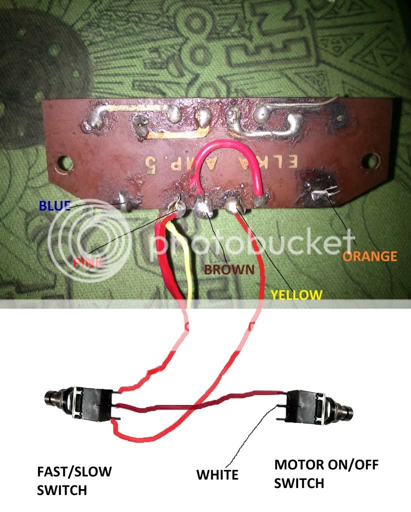
There are six wires comming out from the pedal but the problem is they are not the same colour as yours, everything else looks basicly the same (apart from a bunch of disconnected wires ). The colours are white, yellow, pink, orange, blue and brown. If yellow and white are connected the motor starts working. It also looks like one of the pots has been replaced in the past.
Brown is probably ground right? I was dumb and I didn't take the photo of the inner part (the one in the amp), but from what I remember it is the same (apart from wire colours).
The question is if you can tell me how to wire it up from what you've been told untill now or do i need to take a picture of the part inside the amp so you can see which wire goes where.
I'm really sorry if I am a pain in the ***, but as I said, my circuit reading skills are rubish. I really love to learn by doing so i wan't to do it myself, even if it would be a lot quicker and easier if I asked someone to repair it
EDIT:
Looks like pictures don't work, here are the links:
(also, the thicker red wire goes nowhere, it's just conected there (i think it's for conecting it on the switch)
An externally hosted image should be here but it was not working when we last tested it.
An externally hosted image should be here but it was not working when we last tested it.
There are six wires comming out from the pedal but the problem is they are not the same colour as yours, everything else looks basicly the same (apart from a bunch of disconnected wires
). The colours are white, yellow, pink, orange, blue and brown. If yellow and white are connected the motor starts working. It also looks like one of the pots has been replaced in the past. Brown is probably ground right? I was dumb and I didn't take the photo of the inner part (the one in the amp), but from what I remember it is the same (apart from wire colours).
The question is if you can tell me how to wire it up from what you've been told untill now or do i need to take a picture of the part inside the amp so you can see which wire goes where.
I'm really sorry if I am a pain in the ***, but as I said, my circuit reading skills are rubish. I really love to learn by doing so i wan't to do it myself, even if it would be a lot quicker and easier if I asked someone to repair it
EDIT:
Looks like pictures don't work, here are the links:
An externally hosted image should be here but it was not working when we last tested it.
An externally hosted image should be here but it was not working when we last tested it.
(also, the thicker red wire goes nowhere, it's just conected there (i think it's for conecting it on the switch)
Last edited:
Hello again, as I said I will post some pictures of my pedal. Here they are.
An externally hosted image should be here but it was not working when we last tested it.
An externally hosted image should be here but it was not working when we last tested it.
There are six wires comming out from the pedal but the problem is they are not the same colour as yours, everything else looks basicly the same (apart from a bunch of disconnected wires
Brown is probably ground right? I was dumb and I didn't take the photo of the inner part (the one in the amp), but from what I remember it is the same (apart from wire colours).
The question is if you can tell me how to wire it up from what you've been told untill now or do i need to take a picture of the part inside the amp so you can see which wire goes where.
I'm really sorry if I am a pain in the ***, but as I said, my circuit reading skills are rubish. I really love to learn by doing so i wan't to do it myself, even if it would be a lot quicker and easier if I asked someone to repair it
EDIT:
(also, the thicker red wire goes nowhere, it's just connected there (i think it's for conecting it on the switch)
You're not a pain in the *** at all
It looks like you're PCB was put on fire or something, it looks really bad... You should check first if all your PCB connections are OK. Do you have a DMM (Digital Multi Meter)? Measure the resistance between the connected solder points, to be sure the print tracks are good.
The pot has indeed been replaced, and not by a qualified technician
It is not the correct value (but that's not a very big problem), and the soldering is very bad. It might be better to resolder all connections, or even hard-wire the print (connect the linked solder points on the print with short wires, so broken print tracks are bypassed).There are a few wire connections I can say for sure. The thicker red wire that is hanging loose should be connected to one of the outside pins (not the center one) of the fast/slow switch.
Another (thicker red?) wire should be connected to the solder point in between the two solder points that are connected by the loop of red wire. (the 3rd solder point in the row of four, on your picture). The other end of the wire must be connected to the other outside pin of the fast/slow switch.
the brown wire is probably the ground. To be sure: measure the resistance between this wire and the metal casing of your amp (the metal front panel with all the knobs on it). If it reads (approx) zero, it is the ground wire.
The center pin of the fast/slow switch should be connected to one of the pins of the motor on/off switch.
The ground should be connected to the loop of red wire that is connecting soldering point 2 and 4 on your picture, just connect it to one of the two solder points, it doesn't matter which one.
The rest of the connections is guessing. I really need pictures of the inside of the amp to be sure of them.
Please ask if you don't understand something.
Well i did mess around a little and did some guessing and guess what... I toasted the fuse I decided its probably better to leave the mess around to Ray Charles so i took apart the amp and almost died from all the dust in it, I think it has never before been cleaned and it's pretty old...
I warn you the following picture isn't pretty, I didn't have the time to clean it so I just took a photo. I promise I will clean it properly very soon.
http://shrani.si/f/1Q/GB/14VqD27S/dsc01871.jpg
(every time i see the picture i'm disguasted)
If it's not possible to see the colurs beacouse of the dust here they are (from left to right) Yellow, orange, pink (sort of) and blue
Yea I noticed the circuit in pedal is a bit ''burned'' too, looks like the previus owner was even worse at soldering than me and overheated it.
Well I don't own a DMM, so i'll just bypass the connections as you said.
I think I understand everything you told me so far, and I'm really grateful for all your help.
P.S. As I said i toasted the motor fuse. It's value is 2 Amperes but it says nothing about voltage, do you know what value of V it must be? (i know its probably 250 but i'm not sure)
I decided its probably better to leave the mess around to Ray Charles so i took apart the amp and almost died from all the dust in it, I think it has never before been cleaned and it's pretty old... I warn you the following picture isn't pretty, I didn't have the time to clean it so I just took a photo. I promise I will clean it properly very soon.
http://shrani.si/f/1Q/GB/14VqD27S/dsc01871.jpg
(every time i see the picture i'm disguasted)
If it's not possible to see the colurs beacouse of the dust here they are (from left to right) Yellow, orange, pink (sort of) and blue
Yea I noticed the circuit in pedal is a bit ''burned'' too, looks like the previus owner was even worse at soldering than me and overheated it.
Well I don't own a DMM, so i'll just bypass the connections as you said.
I think I understand everything you told me so far, and I'm really grateful for all your help.
P.S. As I said i toasted the motor fuse. It's value is 2 Amperes but it says nothing about voltage, do you know what value of V it must be? (i know its probably 250 but i'm not sure)
God dammit, just closed my tab when I was ready to post, now I have to type it all over again 
Your fuse is indeed a 2A 250V fuse. Voltage rating isn't that important when you're using standard fuses.
I hope you only toasted your fuse! One of the problems with this Elkatone is that both motor fuses are rated 2 A, but the rectifiers are only rated 1,5 A max! (silly italians).
This means that, before your fuse blows, your rectifier probably blows first! I had this problem in my amp, I had to replace both the fuse and the rectifier.
It's easy to check if your rectifier is OK: just put a new fuse in, leave the motor wires disconnected (don't "guess") and power your amp on. If the fuse blows immediatly, your rectifier is fried. A rectifier is cheap, but it is a lot more difficult to replace than a simple fuse
Now for your pedal wiring:
Your amp is indeed pretty dusty, but that's not a problem. Mine was just as dusty as yours
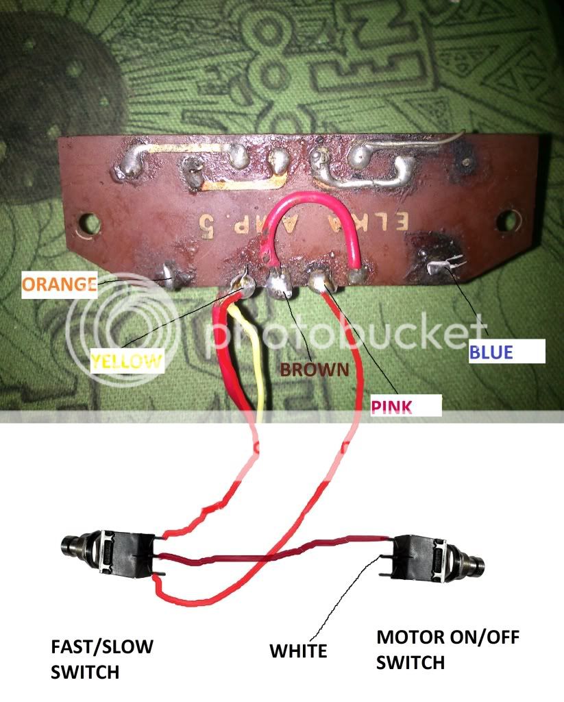
The picture you posted is the picture I needed, it solves the wiring puzzle.
I made a picture with all the corresponding wire colours on it, that's easier than explaining everything in words. The red lines I drew, are interconnections inside the pedal.
Here it is:
The wire that is already connected to your print, (the one where i wrote 'PINK'), is that the pink wire? If it isn't the pink wire, please tell me! That means I made a mistake
Try this first without bypassing the soldering points. If it doesn't work, bypass those points with short wires. If it works, just leave it.
I'm really happy I can help you. My Elkatone was my first ('big') electronics project too, I learned incredibly much from it, more than sitting in class and listening to some physics teacher.
btw, a DMM is really handy and they aren't that expensive. If you're going to do more electronics in the future, you will really need one.
Your fuse is indeed a 2A 250V fuse. Voltage rating isn't that important when you're using standard fuses.
I hope you only toasted your fuse! One of the problems with this Elkatone is that both motor fuses are rated 2 A, but the rectifiers are only rated 1,5 A max! (silly italians).
This means that, before your fuse blows, your rectifier probably blows first! I had this problem in my amp, I had to replace both the fuse and the rectifier.
It's easy to check if your rectifier is OK: just put a new fuse in, leave the motor wires disconnected (don't "guess"
) and power your amp on. If the fuse blows immediatly, your rectifier is fried. A rectifier is cheap, but it is a lot more difficult to replace than a simple fuse Now for your pedal wiring:
Your amp is indeed pretty dusty, but that's not a problem. Mine was just as dusty as yours
The picture you posted is the picture I needed, it solves the wiring puzzle.
I made a picture with all the corresponding wire colours on it, that's easier than explaining everything in words. The red lines I drew, are interconnections inside the pedal.
Here it is:
The wire that is already connected to your print, (the one where i wrote 'PINK'), is that the pink wire? If it isn't the pink wire, please tell me! That means I made a mistake
Try this first without bypassing the soldering points. If it doesn't work, bypass those points with short wires. If it works, just leave it.
I'm really happy I can help you. My Elkatone was my first ('big') electronics project too, I learned incredibly much from it, more than sitting in class and listening to some physics teacher.
btw, a DMM is really handy and they aren't that expensive. If you're going to do more electronics in the future, you will really need one.
Thanks a lot but... The pink one is actually yellow
Okay, let's try it again
The worst thing that could have happened is that the 'fast' pot would have adjusted the slow speed and vice versa.This is where you could have tested the voltages with a DMM: For example, if you measured 25 V on the yellow wire, i would have known where it's supposed to go
But let's try it this way, it should work. Try to solder as clean as possible, if you have any questions, just ask
Hi, I have some bad news. Yesterday when I opened the pedal up and checked the wiring out, I realised I allready did what you told me to do on my own.
Well this seems to be sort of jing jang thing, it's true that i figured out on my own how to properly connect the wires (that's good, my skills have improved, thanks too you), but on the other hand it doesnt work. I tried a couple of times but there was just some crackling niose and toasted fuses. Good thing is that motor is still working, the fuses did their job
It seems I have a bigger problem then just some disconnected wires in the pedal. Looking to the pictures you have posted and trying the wires out I realised that one of the channels does not work. If i connect yellow to white it starts turning, so from what I understand, connecting pink to white should start the other channel, but it didn't (also tried blue to white just to make sure and nothing happend again).
the funny thing is that doing any of this things didn't blew the fuse, but when I soldered it the way you told me to do it did.
I'm confused
Well this seems to be sort of jing jang thing, it's true that i figured out on my own how to properly connect the wires (that's good, my skills have improved, thanks too you
), but on the other hand it doesnt work. I tried a couple of times but there was just some crackling niose and toasted fuses. Good thing is that motor is still working, the fuses did their job It seems I have a bigger problem then just some disconnected wires in the pedal. Looking to the pictures you have posted and trying the wires out I realised that one of the channels does not work. If i connect yellow to white it starts turning, so from what I understand, connecting pink to white should start the other channel, but it didn't (also tried blue to white just to make sure and nothing happend again).
the funny thing is that doing any of this things didn't blew the fuse, but when I soldered it the way you told me to do it did.
I'm confused
That's indeed very confusing. Which fuse is blowing? The main fuse (3,15A), the upper or the lower motor fuse (2A) ?
When you are connecting yellow to white and the motor is turning, does it spin fast or slow?
One of the things you might try is to solder only one half of the print. Start by putting your potmeters in the center position.
If you only solder the yellow, orange, brown and white wires, does the motor turn? Is it possible to adjust the speed with the pot?
If this al works, we know that the yellow/orange side (the fast side, i think?) of the circuit is working OK.
If the fuse blows, unsolder the orange and yellow connections, and solder the pink and blue connections. Check the same things.
This way, we can rule out one side of the circuit (or both, if they both don't work properly).
I'm going to make a schematic (i have a lot of spare time these days).
It would be very handy if you had a DMM. Is it possible for you to borrow one?
When you are connecting yellow to white and the motor is turning, does it spin fast or slow?
One of the things you might try is to solder only one half of the print. Start by putting your potmeters in the center position.
If you only solder the yellow, orange, brown and white wires, does the motor turn? Is it possible to adjust the speed with the pot?
If this al works, we know that the yellow/orange side (the fast side, i think?) of the circuit is working OK.
If the fuse blows, unsolder the orange and yellow connections, and solder the pink and blue connections. Check the same things.
This way, we can rule out one side of the circuit (or both, if they both don't work properly).
I'm going to make a schematic (i have a lot of spare time these days
).It would be very handy if you had a DMM. Is it possible for you to borrow one?
Hi, I'll give you a day off Tommorow I'm going to a diving trip so I won't be home for a whole day and i won't do anything with the amp. I'm sure I can borow a DMM for a day or two, just tell me what connections to check out.
It blows the upper 2A fuse, I will also try replacing the lower one (if i understand you it's for another channel?) It looks well, but just maybe it's faulty (or something) and maybe that's why the other channel doesn't work. Probably not, but worth trying...
Tommorow I'm going to a diving trip so I won't be home for a whole day and i won't do anything with the amp. I'm sure I can borow a DMM for a day or two, just tell me what connections to check out.It blows the upper 2A fuse, I will also try replacing the lower one (if i understand you it's for another channel?) It looks well, but just maybe it's faulty (or something) and maybe that's why the other channel doesn't work. Probably not, but worth trying...
Psychom, just looking at your schematic drawing.. the input longtail pair seems to be traced out differently...if you look at most tail pairs your see signal comes in to the first transistor base pin..followed by the emiter's legs tied together and the collectors are fed with resistors to the -dc rail voltages ..feed back from the amps o/p is linked via a resistor to the second part of the long tail transistor's base pin.
this on is indeed from the old days of amps with small amount of parts to build a amp circuit the 'no frills idea'... any large dc at the o/p would cooked the poor speaker(s)
this on is indeed from the old days of amps with small amount of parts to build a amp circuit the 'no frills idea'... any large dc at the o/p would cooked the poor speaker(s)
The input longtail pair is indeed a bit strange, but i'm sure it's wired this way. When i first got the amp, the 4 transistors were broken and there was 15 V DC at the output. No protection of any kind. But I was lucky, the speakers weren't fried. The amps aren't very good, but at least they are working OK right now.Psychom, just looking at your schematic drawing.. the input longtail pair seems to be traced out differently...if you look at most tail pairs your see signal comes in to the first transistor base pin..followed by the emiter's legs tied together and the collectors are fed with resistors to the -dc rail voltages ..feed back from the amps o/p is linked via a resistor to the second part of the long tail transistor's base pin.
this on is indeed from the old days of amps with small amount of parts to build a amp circuit the 'no frills idea'... any large dc at the o/p would cooked the poor speaker(s)
The fuses are indeed for different channels (fast/slow)Hi, I'll give you a day off
It blows the upper 2A fuse, I will also try replacing the lower one (if i understand you it's for another channel?) It looks well, but just maybe it's faulty (or something) and maybe that's why the other channel doesn't work. Probably not, but worth trying...
If the upper 2A fuse blows, the problem is probably in that circuit. It's highly unlikely that something is wrong with the lower fuse, but hey: just try it
You can try to remove the lower fuse (that isn't blowing) and see if you are able to engage the motor by putting the yellow and white wires together. If it doesn't work, we are sure the problem is in the other circuit (the one with the blue and pink wires).
I've got a feeling that one of the transistors or diodes is bad. I need tot draw the schematic first before I can say more about that. It's not easy, and I'm not home tomorrow, so maybe i'm able to do it monday or so. When I got the schematic, i'll be able to tell you what you need to measure (with a DMM).
And here I am with your schematic
First, i'm going to ask other people to help me, because I don't understand the circuit completely. The other guys on this site are much more experienced than me, so: Please help
I hope you know what a transistor is and what it does, because there are 3 transistors in each circuit. If you don't know how it works, just believe what i'm saying
The schematics for the Fast and Slow circuit are ALMOST identical. The diode in the Fast circuit might be a Zener diode, i am not sure of it.
When you connect yellow and white with the pedal removed, your motor starts turning. This is good, but this also means that V+ voltage (for the fast circuit, about 40V) is going straight to the motor. Your motor must be spinning very fast. This means a very high current draw, around 2A, so your fuse or your rectifier might blow. Do not connect yellow and white for too long.
When you connect the yellow and orange (and white and brown) wires properly to the pedal, you should be able to change the speed. If this is correct, your fast circuit is working OK!
The Slow circuit, well... that's another story. Connecting pink to white while leaving the pedal out of the circuit should put V+ (about 16V) on your motor, it should start turning. But it does not. This means that your 2N3055 transistor is not (or barely) conducting. Your fuse does not blow (this is important, please double check it).
When you connect blue and white, your motor should not be turning, so that's ok.
When you wire your pedal correctly, your fuse blows. Let's ASSUME this has nothing to do with the Fast circuit, but only with the Slow circuit.
If all this is true, there must be a dead short in the slow circuit.
There must be something terribly wrong. To solve this, i need the help of others. What i'm going to say now, is just guessing.
Maybe a wire that's not connected properly. Maybe your pedal PCB is broken and while your 2N3055 is conducting, V+ voltage from the pink wire, is going straight to the ground (brown wire), a dead short.
With a 2 A fuse and your V+ at 16V, a blowing fuse means that the resistance between V+ and ground is only 8 ohms, lower than the motor resistance! A dead short. Or we might have wired the pedal wrong.
You really need a DMM to solve this.
Please note, the above is only true if there isn't a problem with the fast circuit!
I hope some other guys come and tell us what to do
Looks like nobody wants to help us 
I thought of it a bit longer, and i concluded that we really need measurements before we can continue. It's up to you if you want to continue or not. That's your choice
If you want to go on, here are the measurements you need to do.
First of all, measure the resistance to the ground (=chassis) of your pedal wires. Put your black measuring pen on the metal chassis of the amp, and the red one on the wires that go to your pedal. (disconnected!)
Do the same, but this time measure the Voltage with your amp powered on.
These measurements will give a better sight on your problem.
Hi!
Sorry for the late response, i've been away for a few days now. After all I decided that the thing is a bit too much for me. At firts i thought it is just the wiring problem in the pedal, but it turned out it's something more complicated. So since i'm leaving for holidays in a day or two I decided to put it in experts hands.
I got lucky, since my fathers friend has a friendp) who has a lot of expirience in these things. He sure know's what he's doing and it will be fixed soon.
I would like to thank you a lot for all your help, even if it was in vain, since I learned quite alot about electronics i might say. And I was quite happy that when I talked to the guy I could actually tell him what i think is wrong and dind't just say ''somethings not ok, repair it please''
Another funny thing, which i think i didn't mention here. As i was talking too the guy he looked at me and said: ''Well this thing looks at least twice as old as you are, didn't the modern digital keyboard technologies pull you in?'' and i was like: '' I play guitar'' Yep that's right. I play guitar on e-organ amp. And it sounds fantastic!
P.S. Well I would love to play an old hammond organ on it, these things are orgasmic. But since i don't have it....
Sorry for the late response, i've been away for a few days now. After all I decided that the thing is a bit too much for me. At firts i thought it is just the wiring problem in the pedal, but it turned out it's something more complicated. So since i'm leaving for holidays in a day or two I decided to put it in experts hands.
I got lucky, since my fathers friend has a friend
p) who has a lot of expirience in these things. He sure know's what he's doing and it will be fixed soon. I would like to thank you a lot for all your help, even if it was in vain, since I learned quite alot about electronics i might say. And I was quite happy that when I talked to the guy I could actually tell him what i think is wrong and dind't just say ''somethings not ok, repair it please''
Another funny thing, which i think i didn't mention here. As i was talking too the guy he looked at me and said: ''Well this thing looks at least twice as old as you are, didn't the modern digital keyboard technologies pull you in?'' and i was like: '' I play guitar''
Yep that's right. I play guitar on e-organ amp. And it sounds fantastic! P.S. Well I would love to play an old hammond organ on it, these things are orgasmic. But since i don't have it....
Hi! I'm glad you found a solution for it
You tried, and it didn't work. That's not a shame at all, but part of the learning experience! Let's hope the expert finds your problem. When he returns your pedal, ask him what was wrong, then you'll know what the problem really was.
I wish you some more happy jamming ^^
Grtz from Belgium,
Psycho
You tried, and it didn't work. That's not a shame at all, but part of the learning experience! Let's hope the expert finds your problem. When he returns your pedal, ask him what was wrong, then you'll know what the problem really was.
I wish you some more happy jamming ^^
Grtz from Belgium,
Psycho
- Home
- Amplifiers
- Solid State
- Elkatone Amp with problems