Speaker Protection
How did this project turn out? Where did you have that custom enclosure designed and fabricated?
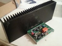
I notice that the Q-Watt has speaker protection designed directly onto the amp PCB. Why is that most speaker protection schemes are placed on a separate board?
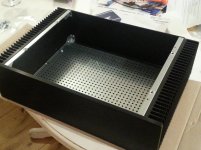
I finally received long waiting enclosure
How did this project turn out? Where did you have that custom enclosure designed and fabricated?
I notice that the Q-Watt has speaker protection designed directly onto the amp PCB. Why is that most speaker protection schemes are placed on a separate board?
Yeah the costs do add up rather quickly. That case looks really nice.
I notice that the Q-Watt has speaker protection designed directly onto the amp PCB.
I did notice one room for improvement on the power supply. You are missing R/C snubbers for the rectifier circuit. Look up quasimodo by Mark Johnson in this forum and he also has a nice ps for chip amps, which could be used for this project.
I notice that the Q-Watt has speaker protection designed directly onto the amp PCB.
One reason is cost, due to duplication of parts like ac fail opto, bjts etc.Why is that most speaker protection schemes are placed on a separate board?
I did notice one room for improvement on the power supply. You are missing R/C snubbers for the rectifier circuit. Look up quasimodo by Mark Johnson in this forum and he also has a nice ps for chip amps, which could be used for this project.
One reason is cost, due to duplication of parts like ac fail opto, bjts etc.
Wouldn't it cost more to have a separate PCB made just for speaker protection?
From a technical and performance perspective, I wonder what the advantages/disadvantages are of having on-board integrated speaker protection built into the power amp PCB. e.g. is it bad idea to put AC on the power amp board? The measured specs of the Q-amp look pretty good, regardless.
Actually if you add up the pcb area for the circuits in duplication, it will be more, > pcb area = > cost.Wouldn't it cost more to have a separate PCB made just for speaker protection?
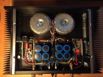
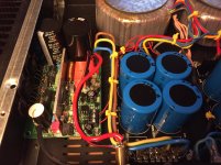
Having the speaker relay on the p/a pcb is a good idea, as it saves on wiring. Wire directly to binding posts.
One fault that I saw was as you noticed, that they did bring the secondary ac up to the pcb. It is possible to reduce hum if it was not their, so it is a easy fix, just put the ac fail opto on the rectifier pcb and use the opto open collector output as your a/c fail signal in.
I am building something similar, but using the LME49830 and the Semelab laterals ALF16N(P)16.
Actually if you add up the pcb area for the circuits in duplication, it will be more, > pcb area = > cost.
Ah, yes. Thanks for pointing that out. Because the Q-Watt PCB is so small to being with, Elektor could get away with integrated speaker protection at relatively low cost.
Having the speaker relay on the p/a pcb is a good idea, as it saves on wiring. Wire directly to binding posts.
To me, this is well worth it. Less wiring inside the chassis.
One fault that I saw was as you noticed, that they did bring the secondary ac up to the pcb. It is possible to reduce hum if it was not their
Yes. it might make more sense to put the speaker protection circuitry on the PSU to help reduce hum to the AC line.... Or spread the protection between power amp and PSU.
that is what I am referring to in,Or spread the protection between power amp and PSU.
This way the ac is not needed on the q-watt pcb.just put the ac fail opto on the rectifier pcb and use the opto-coupler open collector output, as your a/c fail signal in.
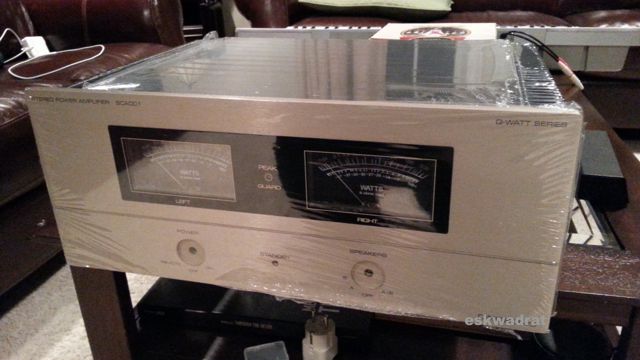
I finally received long waiting enclosure. It looks like $million$ dollars, champagne aluminum front with professionally printed labels and plexiglass window w/artwork for UV meters, looks like hi-end gear from top audio manufacturer. I will be doing final assembly for few weeks now, lot's of fastening prep and work as this is 1st amp of its kind and not everything was designed in Solidworks. Once completed, I will post some pictures. For now just a teaser of what's comin'
An externally hosted image should be here but it was not working when we last tested it.
~Patience is the key ~
Hi there,
I've been looking at this amp for ages too and finally ordered the kit. Looking at the schematics, it is very easy to use symmetrical inputs. The compete amp is built symmetrically so this should be a nice modification.
I'm toying with the idea of building a custom enclosure that would sit right behind the speakers (dual mono design). The enclosure would look like a "tower" with a huge heat sink at the back. The design is still brewing in my head...

I'm very curious how your project evolved. The pictures are no longer available so I was wondering if you could post new pictures and share some of your experiences with the amp.
Ellektor Q-Watt amplifier
Based on the recent posts in the Elektor web site, you'll find lots of new posts, ideas etc., well worth a look.
https://www.elektormagazine.com/labs/q-watt-simple-audio-power-amplifier-110656
The PCB's have been re-released as well as the kits.
Take advantage as the i.c. and power transistors are at the end of their production line.
Elektor Q-Watt amplifier
It might be useful to see the latest posts here:-
https://www.elektormagazine.com/labs/q-watt-simple-audio-power-amplifier-110656
It might be useful to see the latest posts here:-
https://www.elektormagazine.com/labs/q-watt-simple-audio-power-amplifier-110656
I just Googled it and on the first page:
https://www.google.co.uk/url?sa=t&r...sg=AFQjCNFYBvv91GRAoouhJPnXyOXGbw-o4g&cad=rja
https://www.google.co.uk/url?sa=t&r...sg=AFQjCNFYBvv91GRAoouhJPnXyOXGbw-o4g&cad=rja
I recall they posted the article/design for free.
I think you have to be a member to download the gerber/drill files.
I did manage to load up the gerber/drill files okay.
To bad they discontinued the LME498xx devices, stock is dwindling, suggest to get a few spares, like I did with the LME49830.
I think you have to be a member to download the gerber/drill files.
I did manage to load up the gerber/drill files okay.
To bad they discontinued the LME498xx devices, stock is dwindling, suggest to get a few spares, like I did with the LME49830.
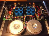
Here's my successfull build:
Great to see one Q-Watt finished Jort... I'm struggling to find the time but it's good to see you completed something very similar.
Which RCA inputs and binding posts did you use? Can anybody recommend something that is decent but not too exotic in price?
Thanks!
Attachments
- Status
- This old topic is closed. If you want to reopen this topic, contact a moderator using the "Report Post" button.
- Home
- Amplifiers
- Chip Amps
- Elektor Q-Watt project