ok,so it will work,i guess
but it is measuring drop on mosfet,right? it is nice idea not to have 0.1 ohm or similar resistor,but im not sure how it will work with measuring on such nonlinear resistor like transistor
can you make version with measuring on 0.1 ohm resistor just in case?
i wonder how would it looks with D or T flip flop instead of AND circuits?
This will reduce the output current by ~25%, course you can change R12

Probably don't need the logic gates at all... I just started drawing on the relay circuit. The relay circuit is better, less resistance, less voltage drop, no non-linear element.

w
")


I hope this post is within the aim of this thread. For experimenting a nice pile of fuses is always useful. However, an electronic fuse would be more comfortable. For low voltage and low current applications, such as solid state preamps and the like, a device switchable for different currents with a short trip time and a modest trip current (the current needed to activate the fuse) would be handy. It should really cut off the current as a fuse, not just limit the current. As far as I could notice, the diyaudio forum did not yet discuss such a design. Googling yielded various options. These days a 'resettable polyfuse' or PTC is a common device that might be used for this purpose is coined in this thead. Alas, for every application a different version is needed. Also, trip time and trip current appears rather high. Another option is a so called Current Limited Switch, that needs additional circuitry, and seems limited to 5V applications.
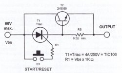
The search also revealed a rather old schematic as attached, that can be found on several places on the net. For instance: DC Electronic Fuse
The description that goes with it is as follows:
“The current flowing through the thyristor T1 (TIC106A = 4A 250V) will sink below the holding level when the current is rerouted through the transistor T2 2N3055. T2 and RS are built into the electronic fuse circuit for this purpose. If the voltage drop at RS exceeds above base-emitter-diode trigger voltage of the T2, the transistor conducts thereby bypassing the thyristor. The resistance value of RS must be at least 0.2 W. It must be dimensioned that the product of RS multiplied by the fuse current value equals to 0.7 volts. Once T2 bypasses the T1, the current flowing through the thyristor sinks below the holding level and the T1 shuts off. This in turn causes the voltage drop at resistor RS to sink below the base-emitter trigger voltage of T2 and the transistor shuts off. The end result is the shutting off of the whole circuit. The DC fuse can be reactivated by pressing the start/reset button. The value of resistor R1 is dependent on the supply voltage. Multiply the supply voltage with 1 KW to get the value of R1. (10k – 56k) Connect the dc electronic fuse circuit to the PLUS line of the consumer load. The voltage drop at the circuit is less than 1 volt.”
The circuit might be old, but it has the advantage of a real fuse and might be equipped with a switch for various resistors to meet the required maximum current. This is what I experienced:
- The resistor R1 for the triggering of the thyristor I used from the drawer (not TIC106) did not follow the given rule, and appeared to be 1K5
- The circuit works, but with a resistor set for 500mA the trip current is over 1.5 A
- Given a minimum of 10mA for the thyristor to stay on for small currents a pull down resistor of say 1K/5W (at 24V) to ground can be added which ensured a minimum current of about 20mA.
- The trip time is long. This is also due to the fact that somehow the transistor T2 does not open at 0,7V exactly, but needs over 0,8V to really switch
- Once T2 switches, it has a strong pulse as an effect, that might be even more risk for the device under test (DUT) than using simply a ptc. The effect can be controlled by adding a simple current limiting resistor/transistor, with the collector to the base of T2. This is effective indeed, but then it is even more hard to get T2 switching.
Can you please suggest a modification to achieve a more civilized behaviour, or may be suggest a better option?
Attachments
Last edited:
Here is the main puzzle of the circuit in post 30.
At 24V input a load of 75 ohm/25W draws about 0.3 A.
According to the given calculation the trigger value of 0.7 V will be reached with Rs = 0.25 ohm.
However, in reality a value of Rs = 13,3 Ohm yields somewhat over 0.6 Vbe of T2. Lowering the load up to a current of 1.5A gives somewhat under 0.7 V.
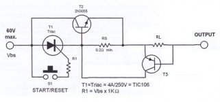
As a next experiment I have added the option of a current limiter at the output as shown in the attached figure. With this limiter set for 1.5A Vbe of T2 goes up to 0.730, which still does not trigger T2 to activate the fuse mechanism.
Can someone please point out what I am missing here?
Arjen
At 24V input a load of 75 ohm/25W draws about 0.3 A.
According to the given calculation the trigger value of 0.7 V will be reached with Rs = 0.25 ohm.
However, in reality a value of Rs = 13,3 Ohm yields somewhat over 0.6 Vbe of T2. Lowering the load up to a current of 1.5A gives somewhat under 0.7 V.
As a next experiment I have added the option of a current limiter at the output as shown in the attached figure. With this limiter set for 1.5A Vbe of T2 goes up to 0.730, which still does not trigger T2 to activate the fuse mechanism.
Can someone please point out what I am missing here?
Arjen
Attachments
I hope this post is within the aim of this thread. For experimenting a nice pile of fuses is always useful. However, an electronic fuse would be more comfortable. For low voltage and low current applications, such as solid state preamps and the like, a device switchable for different currents with a short trip time and a modest trip current (the current needed to activate the fuse) would be handy. It should really cut off the current as a fuse, not just limit the current. As far as I could notice, the diyaudio forum did not yet discuss such a design.
.../....
Can you please suggest a modification to achieve a more civilized behaviour, or may be suggest a better option?
I find this circuit particularly nasty and unpalatable: a huge peak of current first needs to be generated for the thing to turn off, if it does, which IMHO is not guaranteed: a brutal short circuit at the output could generate such a high current that the transistor loses completely its beta, and is unable to turn the SCR off.
Here is a tentative towards something functionally equivalent, but better (and perfectible obviously):
Attachments
Q1, D1 and Q2 form the equivalent of a thyristor, but without having to pass the main current through the base connections.Hi Vasko, Elvee.
Thanks for your kind replies.
@ Elvee: I have send you a PM.
I do not know spice (but have downloaded already the software to start learning), and as a non-EE I might think aloud of what I understand from your suggested circuit.
- Q1 serves as the main pass element that can be shut down when too much current is drawn. Q1 is a fast device.
- Q4 is activated by R6, and, after momentarily closing S1, will activate Q1 (I think V2 is there just for simulation purpose, and in reality S1 should be activated manually). The voltage will rise gradually at turn on.
- When resistor R1 senses too much current Q2 will be activated, which in turn will cause Q4 (and Q1 respectively) to switch off. R1 should be set for the desired maximum current (in my case max 1A).
- D1 is to prevent the shut off current from feedback to the startup.
- BC327 (PNP) resp BC337 (NPN) are generic transistors of appropriate voltage/600mW/100Mhz.
- I suppose R4 = 10 ohm is only added to serve as a load to simulate the circuit?
Is this how you intended it?
All the parts are in the drawer, so I can built it in the next days.
Q4 senses the voltage across R1 and the saturation resistance of Q1.
When the threshold is exceeded, Q4 shuts Q1 down, and this causes a regenerative action, desaturating Q1 very quickly.
R5 / S1 form the reset circuit, but now I see they will not work properly in reality.
They were intended to ensure a continued protection in the event of a reset tentative in the presence of a short at the output.
The circuit could be restarted by shorting B-E of Q4, or C-E of Q1, but none of these methods will provide protection during the action of the switch.
I'll have to think about it; maybe an auxiliary sense transistor, or a RC circuit could do the job.
The transistor were not chosen with something special in mind; they could all have their polarity reversed for example, since it is a two terminal circuit.
The simulation tests the operation of the circuit by first resetting it with V2/S1, then applying a 2 to 20V ramp at the input. When the current into the load R4 is exceeded, the circuit trips.
Here are two resetting circuits that should work.
The first one activates the circuit for a short time, and the second uses an additional transistor to sense the output current and block the restarting if an overload condition is still present.
I havent made detailed calculations with the transistors gain limits, voltages, currents, etc, and component values are just examples.
Attachments
Hi Elvee,
Today I have made your circuit of post 34, and it works fine. I have just send you a pm with some observations of my test jig. Thanks for your mindfulness.
Your second circuit of post 38 looks quite interesting. Tomorrow I will try that. While you are at it: would it be possible to add visual with a led when the fuse is ‘refusing’ to pass current, and for the case when an overload condition is still present?
@ Vasko: BP1 resp. BP2 are momentary switches (push buttons). You can set the limit for the current by adapting the sense resistor (R2 in the first schematic of Elvee, or R8 in his last version). With R2 = 1 ohm the maximum current is about 1A. In my jig I have build the option to switch between two resistors. Vasko, this is really fun; when will you start building?
Arjen.
Last edited:
- Status
- This old topic is closed. If you want to reopen this topic, contact a moderator using the "Report Post" button.
- Home
- Amplifiers
- Power Supplies
- Electronic fuse