An externally hosted image should be here but it was not working when we last tested it.
yet another option to build...I like aardvarkash's circuit very much.
Yes, the name capacitance multiplier is a "misnomer". BTW, before lambasting wikipedia, we need to be aware that this "capacitance multiplier" terminology is not "created" by wikipedia but rather from some "electronic designers" who chose to name the circuit as such. As wavebourn correctly puts it, it is a large R-C with source follower, not a true choke. A good way to filter rectified power. This circuit actually requires another set of capacitors after it handle transients that may occur with class AB amps.
A gyrator would be detrimental in a power supply topology as instead of maintaining a steady voltage at the power supply, it would "choke" or hold back current thus worsening any increased current draw during transients. As I understand it, a gyrator is used to function as a dynamic impedance load for a tube circuit, not as a power supply ripple reducing device.
Wikipedia is a good source of rumor and opinions, but a bad source of reliable information. What is called a capacitance multiplier, does not work as a multiplier: it does not have a capacitive output, strictly speaking. And it does not have properties of inductance, so it is not a choke. It is a R-C filter with a source follower. A good way to filter rectified power, even to bring up output voltage slowly, using relatively small capacitance and big resistance in R-C network for a large time constant.
Yes, the name capacitance multiplier is a "misnomer". BTW, before lambasting wikipedia, we need to be aware that this "capacitance multiplier" terminology is not "created" by wikipedia but rather from some "electronic designers" who chose to name the circuit as such. As wavebourn correctly puts it, it is a large R-C with source follower, not a true choke. A good way to filter rectified power. This circuit actually requires another set of capacitors after it handle transients that may occur with class AB amps.
I saw attempts to use gyrators there, to simulate a choke. It is even worse! P-network tuned on fundamental frequency of rectified power has higher dynamic output resistance than this simple source follower with R-C network in it's gate.
A gyrator would be detrimental in a power supply topology as instead of maintaining a steady voltage at the power supply, it would "choke" or hold back current thus worsening any increased current draw during transients. As I understand it, a gyrator is used to function as a dynamic impedance load for a tube circuit, not as a power supply ripple reducing device.
Hi!
I think the term electronic choke is misleading. As Bas already mentioned, an inductive choke does store energy in addition to it's smoothing effect on the ripple. The electronic choke or gyrator only has the smoothing effect.
To my taste, nothing beats the simplicity and effectiveness of the real choke. Especially for beginners I'd rather recommend to use chokes as filters. These are easier to understand.
Electronic chokes add active devices to the amp. Done right they surely are effective, but also offer potential sources of noise, especially if not applied correctly.
Best regards ... Thomas
Hi,
here is my favorite voltage regulator circuit adapted from Andrea Ciuffoli:
The constant current circuit (D2-D4, R2, T2) makes adjustments straightforward -- no need to recalculate resistor values if you change the zener voltage.
Fred
here is my favorite voltage regulator circuit adapted from Andrea Ciuffoli:
An externally hosted image should be here but it was not working when we last tested it.
The constant current circuit (D2-D4, R2, T2) makes adjustments straightforward -- no need to recalculate resistor values if you change the zener voltage.
Fred
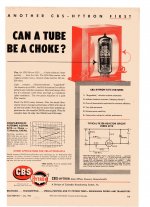
And why not use tubes ? Tubes can be used as filter reactor (chokes) in power supplies,the concept is not new and there even was a type especially designed for that application: the CBS 6216.This small 9-pin miniature high perveance beam power pentode can actually replace a 12H/100mA/350DCR filter choke in a power supply,as illustrated in this 1953 CBS ad below:
Attachments
And why not use tubes ? Tubes can be used as filter reactor (chokes) in power supplies,the concept is not new and there even was a type especially designed for that application: the CBS 6216.This small 9-pin miniature high perveance beam power pentode can actually replace a 12H/100mA/350DCR filter choke in a power supply,as illustrated in this 1953 CBS ad below:
Interesting. Has anyone tried this?
6L6 Sansui AU111 would a choke help?
I just am finsihing a rebuild of the monster Sansui AU111 integrated amp. This is one of the nastest amps I have ever worked on, everything i huge except the space to work.... Had to replace all the filter caps in poower an bias supply. In power supply I used the same values as orignals with higher voltage ratings. In bias I used 100 uf instead of 47 uf. Had to replace in increadible number of coupling (oil and paper caps) to stop DC leakage. Now the problem I have is that with my line voltage (127) I have 530 volts on the plates of the 6l6GC's. I have RCA's in there right now but I don't think anything can last long at that knind of voltage. The power supply uses a voltage doubler. Can I put a choke in before the first set of filter caps to try to get voltage down to aroung 450? Or any ideaas how to deal with this issue?
Thanks
bruce
Use an external bucking transformer to reduce your very excessive line voltage to something more reasonable. A 6.3V or 12.6V transformer would be suitable, the amplifier would probably be happiest with a line voltage of 115 -117V which would have been the nominal at the time it was designed.
Choose a transformer with a secondary current rating at least 50% higher than the load you are powering. Wire the primary across the mains and the secondary in series with the load, reverse primary or secondary connections (not both) if the output voltage is higher than the incoming mains voltage. Put the whole thing in a nice grounded metal box, and make sure there is a fuse on the input end of things..
Choose a transformer with a secondary current rating at least 50% higher than the load you are powering. Wire the primary across the mains and the secondary in series with the load, reverse primary or secondary connections (not both) if the output voltage is higher than the incoming mains voltage. Put the whole thing in a nice grounded metal box, and make sure there is a fuse on the input end of things..
Now the problem I have is that with my line voltage (127) I have 530 volts on the plates of the 6l6GC's. I have RCA's in there right now but I don't think anything can last long at that knind of voltage. The power supply uses a voltage doubler. Can I put a choke in before the first set of filter caps to try to get voltage down to aroung 450? Or any ideaas how to deal with this issue?
1) Try to adjust BIAS for all 4 output tubes, quite possible B+ voltage will go down (to 485V required) due to resistance of power transformer primary.
2) You can try replace 6L6GC with KT66/KT88/6550. They will work fine with 5K transformer. I have no idea how power transformer will handle extra filament current. But you can try anyway.
I have rebuilt Sansui AU-111 from scratch, with 6550 and 3.9K audio transformers of my own design. Works great, now looking for suitable chassis.
3) AU-111 draws about 40-45 mA per output tube when idle, so 50 Ohm choke (rated 5H @ 400mA) will drop around 8 - 10V (pre-amp mA consumption is just tiny). If space allows, you may try to use CLCLC filter with 2 chokes in series to drop B+ voltage. I think horizontally mounted fixed air gap toroid chokes should fit somewhere on top plate (I'm not joking, mount them atop of filter caps and power transformer, and connect via screw terminals), as they require only 90x60 mm footprint for each. I don't have original Sansui AU-111 so I have no exact measurement of space inside, this is just my guess.
4) Simplest option - wirewound resistor.
5) Replace power transformer with custom-built.
Follow up to sugggestions
Thansk great suggestions- It is wonderful to have som many ideas. A couple clarifying questions
The bucking transformer- I have room for a transformer. Amp is fuses at 4 amps and I guess the current consumption is probably 200-400 MA for the whole amp, but that is a guess. So would a 12.6volt 1 amp secondary be enough for series with the secondary? I assume it would be inserted before the voltage doubler diodes.
I may try the 6550's although the bias voltage available is around -55 volts and then goes through 68K resistors to the grids. I still am worried about 550 volts on non NOS output tubes.
The series resistor idea might actually work as there is a place on the top of the chassis that I could mount a 50 Watt resistor Any idea where to start?
Thanks again,
bruce
I may try the 6550's although the bias voltage available is around -55 volts and then goes through 68K resistors to the grids. I still am worried about 550 volts on non NOS output tubes.
Use voltage doubler in BIAS circuit.
- Status
- This old topic is closed. If you want to reopen this topic, contact a moderator using the "Report Post" button.
- Home
- Amplifiers
- Tubes / Valves
- Electronic choke