Nice clean build.
Yup, the PS trafo will run warm if not hot in a SE amp, I was concerned too but don't worry.
What rectifier tube are you using? If its not a 5AR4 try one of these (Sovtek ones seen to work well) and you will get some more volts on the B+. Also the lower value cathode resistor may pull some more amps and drop the b+ a little.
Cathode to earth is more like 12v on mine I recall.
B+ and how to
Hi to all!
Actually, I got the notification a little bit late, and I was even later with replying (should invent a time-flow enhancing machine to make 2 hours of free time into 4 hours where everyone else around me is frozen...).
If you are using a 5U4G, the B+ is most probably some 15V lower than it would be with a 5AR4 (GZ34). Therefore, just replacing the rectifier should do the B+ trick -- but the 5U4G sounds better than the 5AR4 (obviously this is an individual taste statement, but most would agree). You can get interesting results as well with a GZ37 (good looking, too).
When it comes to the 270 ohm Rk for the output tube, if you use a 300 ohm resistor, the current draw is lower therefore the B+ which is unregulated will tend to rise. BUT, this is not the correct way as the tube will draw less current and not operate at the "designed" point.
Furhtermore, the warm power tranny could mean that it is not powerful enough for the task (depending on how warm). I personally prefer over-sizing the PS. It is possible that you are not getting the B+ as wished because the circuit draws more current than the power tranny is able to give (thus a reduction of AC output... etc.)
Check all of the above and let us know what does the trick.
Regards,
Alex
ALEX KITIC THE MAN!
HI ALEX.
Well the transformer is 300-0-300 as the schematic call for, am very new at this 3 moth ago i did not know how to read a schematic but i was determined to learn about tube technology .anyway i try to stay as close as i can to your schematic accept for the choke and the cathode resister which i will get the right one (270ohms5watt) soon .
as for the transformer i do have 375-0-375 that i can use if you think is a good choice.
BTW: MR ALEX thanks for sharing the RH84 as for now i'm very impress with it and because its my first built ever it is extra special .
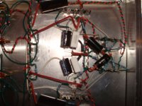
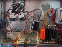
oh and here's another pix please let me know if i need to change things around .
HI ALEX.
Well the transformer is 300-0-300 as the schematic call for, am very new at this 3 moth ago i did not know how to read a schematic but i was determined to learn about tube technology .anyway i try to stay as close as i can to your schematic accept for the choke and the cathode resister which i will get the right one (270ohms5watt) soon .
as for the transformer i do have 375-0-375 that i can use if you think is a good choice.
BTW: MR ALEX thanks for sharing the RH84 as for now i'm very impress with it and because its my first built ever it is extra special .
oh and here's another pix please let me know if i need to change things around .
Attachments
calculating the B+
Hi to all!
While I am at it, let me refine this B+ and power transformer issue. Very often we find ourselves with a power transformer at hand, i.e. 375-0-375 and do not know whether it will fit the design somehow.
The best way is to make a quick calculation, possibly software assisted, in order to get an idea of the usability of the transformer, and the rectification options at hand.
I personally use and highly recommend the PSUD II -- take a look at the authors page:
http://www.duncanamps.com/psud2/index.html
When you do have some experience, almost immediately you can ***** that 375-0-375 is very good for this amp, particularly used in an LC configuration with some inefficient but good sounding direct heated rectifier tube like the 5Y3 (yes, powerful enough for the RH84, and possibly the most refined option depending on the tube itself...).
Try and let us know!
Regards,
Alex
5Y3 for RH84 simulation
Just to give an idea to newbies, please find herewith attached a power supply file for use with PSUD2: the presumed values are 100mA current draw, 375-0-375 transformer capable of 100mA, 5Y3 rectifier tube... download the software and the file and use it to simulate the values.
One might say that this is not EXACT, and it really is not (too many assumptions, too little measurement derived values) -- but the actual values will basically correspond to what reported by the simulation.
Regards,
Alex
PS
Change the extention of the file from .txt to .psu")
Just to give an idea to newbies, please find herewith attached a power supply file for use with PSUD2: the presumed values are 100mA current draw, 375-0-375 transformer capable of 100mA, 5Y3 rectifier tube... download the software and the file and use it to simulate the values.
One might say that this is not EXACT, and it really is not (too many assumptions, too little measurement derived values) -- but the actual values will basically correspond to what reported by the simulation.
Regards,
Alex
PS
Change the extention of the file from .txt to .psu
Attachments
rh6550
Alex, did you ever complete a design for a 6550/kt88 version? I built a rh84 using good parts (all lundall iron, including lclc power supply), and it is a fabulous amp. I did use a slightly different op point - I like the way it sounds with el84's at 35-40 ma, so I settled on cathode r 220. I use it my main system, it sounds as good as either my 2a3 or 300b amps, and is certainly less expensive to use different tubes!
Alex, did you ever complete a design for a 6550/kt88 version? I built a rh84 using good parts (all lundall iron, including lclc power supply), and it is a fabulous amp. I did use a slightly different op point - I like the way it sounds with el84's at 35-40 ma, so I settled on cathode r 220. I use it my main system, it sounds as good as either my 2a3 or 300b amps, and is certainly less expensive to use different tubes!
RH88
Hi, JimW!
Indeed I did it, quite a long time ago Very few people got the schematics from me, and I am not quite sure whether anyone has built it.
To cut a long story short, please check my posts in another thread: "Used Tube Amps, second life.." (I do not know how to link it directly, but anyone can find it).
Mentioning the 300B, you might get even more intrested: this is a new and different "pair of shoes".
Regards,
Alex
PS
Thanks for the compliments and the appreciation of my designs.
Hi, JimW!
Indeed I did it, quite a long time ago
Very few people got the schematics from me, and I am not quite sure whether anyone has built it.To cut a long story short, please check my posts in another thread: "Used Tube Amps, second life.." (I do not know how to link it directly, but anyone can find it).
Mentioning the 300B, you might get even more intrested: this is a new and different "pair of shoes".
Regards,
Alex
PS
Thanks for the compliments and the appreciation of my designs.
rh84 "hot" transformer
ok guys .
i have come to a conclusion for my low b+ and the hot transformer , after closer inspetion the trans also have some "buzzz" not a good sign, after all it did come from an older amp i have so am going to get a new one (hammond 600vct@250ma--5v@4a sec--6.3v@8ma) i think this should be plenty.
let me know what you guys think.
thanks
Tim
My trafo is an Edcor with 500v CT @250ma (I have SS rectifiers) and it really only gets warm compared to my "other" SE amp. I also built an RH 84 for a friend with tube rectifier and an Edcor 600v ct @200ma which also only runs warm. So, yes, in my experience that will work fine in terms of its current capacity at least.
Alex,
Do you want to share the schematic for the 300B? I've used nothing but the 300B for the last 20 years (ok I'm showing my age) and have listened to every SET circuit I could in that time. I would love to play with it. Send it to my email.
Currently running a 6SN7 to a 45 which drives the 300B into deep Class A, parafeed output. The 6SN7 and 45 are CCS, the 300B is choke loaded.
RH second generation
Dear all,
all of those who would like to try building one of the two RH second generation amps, please send me an email and I will send you the schematics.
You can find my email on my website (www.tubeaudio.8m.com)
Just a reminder: the schematics are two, one for the 300B (RH300B) and the other for the KT88/6550. I have never build the 300B amp, but then again I have also never built the RH807 which was specially designed for my friend Elvis
The 300B of course will work in the only possible configuration, as a DHT -- while the KT88 can be used either as beam tetrode, or in triode mode. As previously mentioned about the amp in other forums, it is advantageous to use the tetrode mode as you get more power without loss in sound quality (actually sounds better in tetrode mode, if it matters).
In the 300B case, the main reason to adopt the RH 2nd generation schematics is obatining a result (and most probably, a sound characteristics) much different than the regular expectancy from 300B tubes.
Regards,
Alex
low B+ and now highB+
hi guys
after a few days trying to figure out my low B+ (250) i decided to upgrade to a beefier Power transformer 600ct@250ma ,overkill i know.but anyway now B+ is 354, plate@345 and the cathode @11v so after the math im getting (i hope this is right) 11v/300ohms=37ma
plate dissapation@11.99
is this too high?
is this ok?
what my solution?
my buddy sugesst puting 100ohms before the choke to lower the
B+.
Thank
TIM
I would not be too concerned with those plate voltages, assuming the overall dissipation is kept within reason and there are no visible signs of overheating (red glow on the plates). I have operated 6p14p (Russian EL84 equivalents) at over 400 volts on the plate, both in fixed bias and cathode biased amplifiers. It might be worthwhile to investigate whether the 12AT7 is still operating at an optimal point with the higher supply voltages.
I would hesitate to drop the B+ by simply burning up the excess volts in a big resistor. You'll make a lot of waste heat and add a lot of unwanted impedance to the power supply. Instead, maybe consider reducing the value of the capacitor between the choke and the rectifier tube.
Lowering the value of the first cap (it is shown as a 47uF, 450V part on A.K.'s schematic) will move the whole power supply closer to operating as a choke input filter. If you are seeing 354V B+ with 47uF, I'm guessing something around 2uF will get you the 300V you want.
Thanks TY
hey thanks for the reply that really make me feel allot better, i was very concern about the high plate voltage but also did read that some do run them pretty high i wasnt sure .
BTW: i also measure the voltage at the anode of the 5u4 and it's @ 390
that seem odd to me because the PTX is 600CT@250MA why am i getting 390V? then again im a newbie .
i played it for an hour or so to see if anything is ok , i didnt notice any redplating at all, the tube i have in it are old magnavox that tested pretty strong i also notice the sound is alot faster than when the old trans was in there. although i will try the smaller cap like you recomended to see if i can get close to the desired B+(300v)
i will report back as soon as i get to it.
thanks again for all the help.
TIM
i will report back as soon as i get to it.
thanks again for all the help.
TIM
Re: Thanks TY
I expect that transformer manufacturers give the output voltage rating under full load. If you don't pull the full 250 mA out of it, you'll likely get higher than 300-0-300. In your case, you are getting 390-0-390.
Is your PT a Hammond? Hammond transformers have a reputation for putting out way more volts than they are rated. Another issue with the Hammond units is the 200 series power transformers are all designed for 115VAC primaries, but nowhere in the US will you actually find a wall outlet with the voltage that low. My line voltage usually runs upwards of 125VAC or more.
It might be worthwhile to check the 5.0V and 6.3V filament windings while the amp is running and verify they are not running too far above spec. Over volting the tube filaments can substantially shorten the tube's life.
tim614 said:BTW: i also measure the voltage at the anode of the 5u4 and it's @ 390
that seem odd to me because the PTX is 600CT@250MA why am i getting 390V?
I expect that transformer manufacturers give the output voltage rating under full load. If you don't pull the full 250 mA out of it, you'll likely get higher than 300-0-300. In your case, you are getting 390-0-390.
Is your PT a Hammond? Hammond transformers have a reputation for putting out way more volts than they are rated. Another issue with the Hammond units is the 200 series power transformers are all designed for 115VAC primaries, but nowhere in the US will you actually find a wall outlet with the voltage that low. My line voltage usually runs upwards of 125VAC or more.
It might be worthwhile to check the 5.0V and 6.3V filament windings while the amp is running and verify they are not running too far above spec. Over volting the tube filaments can substantially shorten the tube's life.
- Status
- This old topic is closed. If you want to reopen this topic, contact a moderator using the "Report Post" button.
- Home
- Amplifiers
- Tubes / Valves
- EL84 SE design recommendations?