Bas Horneman said:Just keep the 10k for the moment and see what it sounds like.
Ps...did you try to post another picture? I don't see the rp in green...
Yes, here it is.
Attachments
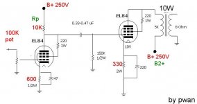
I'm not sure if there is a standard notation. But the plate resistor I think should be called Ra (Resistance Anode)
The Rp is the internal resistance of the tube? (Someone please correct me if I'm wrong)
Anyway keep the Ra 10k for the time being.
And yes, if you can add additional filtering in the form of an RC network for the driver stage and feed that with a higher B+
The Rp is the internal resistance of the tube? (Someone please correct me if I'm wrong)
Anyway keep the Ra 10k for the time being.
And yes, if you can add additional filtering in the form of an RC network for the driver stage and feed that with a higher B+
Generally speaking, fixed values (like load resistors) are represented by upper case letters while dynamic values (like plate resistance) use lower case.
For the subscript, both 'a' (anode) and 'p' (plate) are used, though it seems that 'p' is used mostly by people in the US. Worldwide, 'a' is more common.
So a load resistor can be either Ra or Rp. The plate (err... I mean anode) resistance of a tube can be either ra or rp.
If you're an old codger that still programs in FORTRAN then everything is upper case.
-- Dave
Thanks for the explanation.So a load resistor can be either Ra or Rp.
Dave Cigna said:....If you're an old codger that still programs in FORTRAN then everything is upper case.
[/B]
No I programme COBOL
")
Thanks for your advice. However, I quickly looks on a local electronic book here and a few paragraph mention that the ratio of Rp(or Ra) of the first stage and the Rg of the 2nd stage should be around 3-5 for Cap interstage coupling. Have you ever heard that golden rule?
And go thru my schematic collection (~ 14 ones) and all of them comply with that guide line. In the circuit I just posted, the ratio 150K/10K = 15 which is much higher. Will it be any problem esp. on stabability & sonic degrade?
Yvesm said:A quick check with Tube CAD.
.....
Is the Tube CAD a computerized aid design software? Is it a freeware/shareware? Any hint where I can get it (at least for trial)? Thanks.
It's not freeware, but it's pretty cheap. You can get it through www.tubecad.com or www.tubesandmore.com .
The "free" way to do this is by the use of load-lines and graphical construction.
Think of that as an absolute minimum. Tubes generally show the least distortion with the highest possible loads.
The "free" way to do this is by the use of load-lines and graphical construction.
the ratio of Rp(or Ra) of the first stage and the Rg of the 2nd stage should be around 3-5 for Cap interstage coupling.
Think of that as an absolute minimum. Tubes generally show the least distortion with the highest possible loads.
- Status
- This old topic is closed. If you want to reopen this topic, contact a moderator using the "Report Post" button.
- Home
- Amplifiers
- Tubes / Valves
- EL84 as both driver and output stage.