Here it is a useful link at the very beginning of this thread about “it cannot be done”.
EL84 and 6V6 in parallel???
EL84 and 6V6 in parallel???
Like you, I don't see a problem with the tubes sharing the primary of the OPT, but that's not 'proof' by far.
Looking at the datasheets of the EL84 and the 6V6 I think that for class AB, and all tubes in pentode mode, Raa = 4K would do fine for a guitar amp.
The differences are the required bias voltage and the required input voltage for full power.
The 6V6's need a higher negative grid voltage than the EL84's (roughly -19 V for the 6V6 against -10.5 V for the EL84, but these numbers are based on the data for class AB with cathode bias, while I think that when combining them fixed bias is necessary).
The 6V6's need more input voltage for full power than the EL84's.
It looks to me that with the ‘trick’ in the Mesa amp in post #107, so using voltage dividers for the EL84’s, you can both lower their bias voltage and their input voltage. I would calculate the whole thing for proper bias. Maybe that either the EL84’s or the 6V6’s will not produce their full potential power when fully driven, but my guess is that this possible ‘gap’ will not be large.
I didn’t read the whole thread from the beginning, so if I wrote things that are already been put forward by others, I’m sorry for that.
Thought some more about it.
I've never used fixed bias. But it looks to me that the safe way (so not necessarily the best way for lowest distortion/best sound/etc.) to translate the data for class AB operation with cathode bias to operation with fixed bias, is to calculate the required bias voltage at full power, so full current draw.
The 6V6’s as a pair draw 105.5 mA at full power over a common cathode resistor of 250 Ohm (source: Brimar datasheet for the 6V6G). So the required bias voltage has to be at least 0.1055 x 250 = -26.4 V.
The EL84’s as a pair draw 114 mA at full power over a common cathode resistor of 130 Ohm (source: Philips datasheet for the EL84). So the required bias voltage has to be at least 0.114 x 130 = -14.8 V.
So those bias voltages could be the input for calculating the required voltage dividers for the EL84’s. Ofcourse you have to respect the maximum values for the grid resistors (EL84: 330K max. for fixed bias but I would go a bit safer, like 220K).
I think a stabilized supply for the bias voltage is wise. Compared to most bias supplies, this one will have to pass some current because of the voltage dividers. It would also make it possible to design in two adjustable resistors into the voltage dividers for the EL84’s so you could tweak it a bit when you’ve built the amplifier without changing the bias voltage at the output of the bias supply in the process.
Both the 6V6's and the EL84's as a pair require Raa = 8K at a B+ of about 300 V. They draw almost the same amount of current with no input signal. At full power the EL84's draw more current than the 6V6's but that is mostly caused by the relative high screen grid current of the EL84's at full power.
So I think of it as connecting 4 x 6V6 or 4 x EL84 in push-pull. I just half the Raa from 8K to 4K.
So I think of it as connecting 4 x 6V6 or 4 x EL84 in push-pull. I just half the Raa from 8K to 4K.
If it´s not so difficult, why aren´t you just doing it,instead of asking for 127 posts? (by now).
You can´t both be drowning, asking for help, and at the same time claiming "swimming is easy" or that you are a competent swimmer, pick one or the other.
As of "I can put two tubes in parallel and so be it" , yes, you can.
You can also put a 4 ohm and a 16 ohm speaker in series or parallel, why not?
But forget about any reasonably balanced result, which is the problem here.
Mesa did its homework, you should too.
Hint: use datasheet supplied tube curves to solve your problem, there´s nothing else needed.
I think the formula is the same as the formula for calculating two (or more) paralleled resistors, so 1/Raa(pentode pair 1) + 1/Raa(pentode pair 2) = 1/Raa(total).
This is possible with pentodes because as a general rule there is a pretty hard relation between the value of the optimum load, the anode current and the anode voltage.
For single power pentodes in class A the formula for the optimum load (here meaning: maximum power) is: Ra = Va / Ia. Translated to class A push-pull operation you would get: Raa = 2 x (Va / Ia) but in practice you will see that Raa is somewhat lower. But the realtion still holds more or less.
Maybe my approach is ‘cutting conrners a bit’ but as a rule of thumb it doesn’t look that bad to me.
For combinations of triode and pentodes, this approach is not valid, because the optimum load (here meaning again: maximum power) for triodes is: Ra = 2 x Ri (Ri = internal resistance in the chosen working point). How you have to combine these two different formula’s into one is for tomorrow (or later…or for smarter forum members).
Juan Manuel, i just posted 9 times on a 10 years old thread. So you feel mature posting with this bitterness without even being sure of what you say?If it´s not so difficult, why aren´t you just doing it,instead of asking for 127 posts? (by now).
I'm not drowning at all. Don't make the story bigger than what it is. I declared I don't know how to calculate it and I told that, being those two valves not so different, they would probably accept the lowest-higher B+ and half the highest Raa. Bias and signal solved with the voltage divider. I also told that I would have posted my way of doing it, and I'm doing it.You can´t both be drowning, asking for help, and at the same time claiming "swimming is easy" or that you are a competent swimmer, pick one or the other.
Again childish bitterness. You demonstarted in the past to be better than this.Mesa did its homework, you should too.
Is this really only because you told "it can't be done. Period." but you were wrong?
Please, keep away the bitterness. Come back as you used to be.
This is possible and reasonable, what I would like to know is how theory can help on correctly calculate this.I think the formula is the same as the formula for calculating two (or more) paralleled resistors, so 1/Raa(pentode pair 1) + 1/Raa(pentode pair 2) = 1/Raa(total).
Thanks why I proposed a 23% UL tap: keep the power high while simplifying the matching of the loads, as UL does.This is possible with pentodes because as a general rule there is a pretty hard relation between the value of the optimum load, the anode current and the anode voltage.
I agree with your approach, in my next post I will add what I would do, but I would like to be able to combine very different tubes.Maybe my approach is ‘cutting conrners a bit’ but as a rule of thumb it doesn’t look that bad to me.
Yes, but if you have aver played a Simulclass, maximum power is not the goal, but it's the richness of the harmonic content, if this is something that can be universally understandable.For combinations of triode and pentodes, this approach is not valid, because the optimum load (here meaning again: maximum power) for triodes is: Ra = 2 x Ri (Ri = internal resistance in the chosen working point). How you have to combine these two different formula’s into one is for tomorrow (or later…or for smarter forum members).
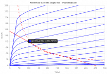
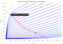
In attachment there are the two loadlines, both tubes with 320 V, 23%UL, 33 mA at idle and 8 kOhm Raa.
6V6s alone would contribute with:
4.3 W in class A
13 W in class AB1
around 20 W in class AB2 (at g1=+10V)
Va = 90 V when g1=0
Ia = 114 mA when g1=0
g1 at idle = -23 V
EL84s alone would contribute with:
4.3 W in class A
18 W in class AB1
Va = 51 V when g1=0
Ia = 136 mA when g1=0
g1 at idle = -13 V
So if I swing the 6V6 with 23 Vp, I need a voltage divider of 13/23 = 0.565 times to fully drive the EL84s, like a 47 kOhm + 10 kOhm to ground. This will increase the EL84's g1 voltage reference too, stabilizing the bias.
I would say that the combination of the two different pairs in parallel will cross the g1=0 curve at around 70 V and 250 mA.
Now, imagine that we want to make the 6V6 work with 10 kOhm Raa and the EL84 with 8 kOhm.
Is it correct to say that, with previous data, I can have a primary of 4 kOhm Raa where I connect the EL84s, and then 2 kOhm more for the 6V6s anodes?
Attachments
To your last question: I guess so.
Driving the 6V6's AB2, so with grid current occurring in part of the signal swing, looks problematic to me. It causes very unpleasant high order distortion to begin with. Furthermore it puts an enormous strain on the driver stage. You're already proposing very low value grid resistors. If on top of that the driver has to furnish the extra on/off going grid current for AB2 operation, I think it will have to be quite a special/beefy/low impedance driver. And the bias supply has to be a very stable one under these conditions.
I never use simulclass, LTSpice, etc.. I'm stil learning (and that will hopefully continue for some time), so to me it seems better to do all the drawing and calculating myself. I do use TinyCad for drawing schematics, but that's just modern 'pen and paper'.
How come there's a kink in the loadlines?
About combining triodes and pentodes: Probably the total Raa can be calculated with the same formula as for pentodes. But unlike (ideal) pentodes, the anode current of a triode depends also on the anode voltage. If and how this causes new problems (like in: you can't combine any triode with any pentode) is not clear to me (yet?).
Last edited:
Good, then we all hope there will be some knowledged people explain us how to correctly calculate it.To your last question: I guess so.
This can be achieved with Powerdrive without strain on the driving stage, but whilst 6V6 is designed to work in AB2, so grid1 is supposed to resist that, EL84 isn't.Driving the 6V6's AB2, so with grid current occurring in part of the signal swing, looks problematic to me. It causes very unpleasant high order distortion to begin with. Furthermore it puts an enourmous strain on the driver stage. You're already proposing very low value grid resistors. If on top of that the driver has to furnish the extra on/off going grid current for AB2 operation, I think it will have to be quite a special/beefy/low impedance driver. And the bias supply has to be a very stable one under these conditions.
Just one note: I haven't proposed any grid resistor value, but this could be the trick to make the 6V6 going into AB2 while keeping EL84 in AB1.
It's the transition from tubes conducting 100% of the time (plotted as Raa/2) and tubes off for part of the cycle (plotted as Raa/4).How come there's a kink in the loadlines?
Just one note: I haven't proposed any grid resistor value, but this could be the trick to make the 6V6 going into AB2 while keeping EL84 in AB1.
From post #132:
So if I swing the 6V6 with 23 Vp, I need a voltage divider of 13/23 = 0.565 times to fully drive the EL84s, like a 47 kOhm + 10 kOhm to ground. This will increase the EL84's g1 voltage reference too, stabilizing the bias.
Seen from the bias supply and the driver, all the bias resistors will be in parallel so the total resistance even gets way lower than 57K (47K + 10K).
I'll leave it to other forum members than because it looks like I can't help you further. Succes with your project.
Last edited:
You are right, I have to admit I was only suggesting the ratio (and it’s even wrong!  ), without thinking about the exact values. In any case being in pentode mode, the impedance can be raised more without any risk of HF roll off. Grid leak and proper driving of g1 would be upper limit.
), without thinking about the exact values. In any case being in pentode mode, the impedance can be raised more without any risk of HF roll off. Grid leak and proper driving of g1 would be upper limit.
Last edited:
I've found something here about mixing classes of operation and tubes, but not exactly what I'm looking for.
The Tube CAD Journal: Mixed Mode Amplifiers
The Tube CAD Journal: Mixed Mode Amplifiers
In all the mixes, the goal would be the same: to create a simple, seamless sounding push-pull amplifier that uses only a single input and phase splitting (and driver) stage per amplifier. This goal can met with an near infinite mix of output tube types and bias points. One example is using a pair of EL34s for the Class-A grouping and KT88s for the Class-B pairing. Another example might be using a pair of 300Bs for the Class-AB grouping and 211s for the Class-C pairing.
- Status
- This old topic is closed. If you want to reopen this topic, contact a moderator using the "Report Post" button.
- Home
- Live Sound
- Instruments and Amps
- EL84 and 6V6 in parallel???