Hi Rootz,
Thanks for the suggestion to increase feedback resistors, in fact Ian told me the same things in post 1728 and I have followed that recommendation.
I agree also for the driving voltage, I answered too quickly without thinking enough
If nobody find an error on the design, I will send the PCB files to the subcontractor and let you know when it will be assembled...
Marc
Hey, finally finished my schematic in kiCad, probably going to end up building it P2P, but right now working on sourcing all the parts. Could you guys look over this and make sure everything looks good before I finish sourcing and actually order the parts? Attached are the schematics and the KiCAD project.
I did a brief check your .pdf schematic just now.
You have the shunt feedback from the ultra linear (screen) taps. Most guys have concluded that it is better from the output tube anodes. If you do a pcb layout cater for either. If building point to point then use the anode connection initially. Easy to change later to try the UL connection point instead.
That is the post #602 schematic rather than the post #604
Cheers,
Ian
Last edited:
So from my understanding, these put out about 10WPC, I'm planning on building a pair of monoblocks, and hooking them up to large, high-sensitivity speakers, specifically the Fusion 12 Tempests by Jeff Bagby, which come in at 98dB/2.85V/1M. Will this be enough power for them to get really loud in a medium room, and if not, could I get some speaker recs?
Also, I've put the schematic and BOM up on my site, with the mentioned changed by Ian to the feedback taps. Just threw them up on a github page: tobycyanide.github.io
Also, I've put the schematic and BOM up on my site, with the mentioned changed by Ian to the feedback taps. Just threw them up on a github page: tobycyanide.github.io
Last edited:
Hi,
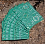
I am back after some time on the Merlin Blencowe RIAA preamplifier (see this thread : http://www.diyaudio.com/forums/tubes-valves/308369-merlin-riaa-preamp-4.html ) and while I was waiting for the RIAA amplifier PCB, I take some time to check the EL34/6CA7 version of the Baby Huey, and the break was very useful because when I came back to my design, I have found that I used a wrong library for the output tube with a bottom pattern instead of the top on
Now I have corrected this and made some optimisation on the layout and I hope to send it to the PCB shop next week...
You ca find the latest version here and I will be very happy if there is no more mistake or if in case there is an other one someone find it and let me know
Cheers,
Marc
Attachments
OK - that chassis I have for the next build has a Tango Output Tranny with an Raa of 8K and 25 watt Rating.
It will be a 6SL7 + KT66.
Hmmm, I wonder what happend to this!
I've got a bunch of very nice KT66, some 6SL7 and a set of suitable trannies. Would be great if I could make a Baby Huey out of that. And ideas, pointers, suggestions?
Ok. Do you think the 6SL7 + KT66 (or maybe 6SN7 + KT66) is a promising combo in a Baby Huey configuration? You seemed a bit sceptical about using the 6SL7 + 6V6G in an earlier test (post #3). That's why I am wondering if it's worth pursuing the 6S*7 + KT66 any further with the Baby Huey, or if I am better off going another route.
On post #198 Ian (Gingertube) give an exemple of a Music Angel amplifier with 6SL7 and EL34 converted in Baby Huey version... On my previous post above I made a similar version with a 12AX7 input tube. I don't see any reason why that should not work with a 6SL7, however I will not use the 6SN7 which has a much lower gain !
Marc
Marc
Thanks for pointing me to these posts, good stuff. I like the MosFET buffers to drive the power tubes!
Any idea about how much the total gain is with the schematic in post #198?
Modifying the schematic of post #198 to (1) change from EL34 to KT66 and (2) maybe skip the input/gain tube shouldn't be a big deal.
Any idea about how much the total gain is with the schematic in post #198?
Modifying the schematic of post #198 to (1) change from EL34 to KT66 and (2) maybe skip the input/gain tube shouldn't be a big deal.
After spending a lot of time on the modified Merlin Blencowe RIAA amplifier and running in trouble with the power dissipation of the MOSFET source follower, going from the ZVN0545 to the STQ3N45K3-AP which is specified at 3 W but still running very hot at 200 V and will probably die at 300 V, I have decided to redraw the schema and the PCB of the EL34 Baby Huey version and to implement a TO220 pattern for the MOSFET stage.
This way I will have more freedom to select the best solution and I will buy the following devices that seem to fit the requirement, specifically for a very low Crss :
FQPF2N60C Vds=600 V, Id=2 A, Rds=4.7 ohm max, Crss=4.3 pF
STF2N80K5 Vds=800 V. Id=2 A, Rds=4.5 ohm max, Crss=0.5 pF !!!
STF7N60M2 Vds=600 V, Id=5 A, Rds=0.95 ohm max, Crss=0.68 pF !!!
I hope that one of these will give the best result Here are the corrected schema and PCB...
Cheers,
Marc
This way I will have more freedom to select the best solution and I will buy the following devices that seem to fit the requirement, specifically for a very low Crss :
FQPF2N60C Vds=600 V, Id=2 A, Rds=4.7 ohm max, Crss=4.3 pF
STF2N80K5 Vds=800 V. Id=2 A, Rds=4.5 ohm max, Crss=0.5 pF !!!
STF7N60M2 Vds=600 V, Id=5 A, Rds=0.95 ohm max, Crss=0.68 pF !!!
I hope that one of these will give the best result
Here are the corrected schema and PCB...Cheers,
Marc
Attachments
EL34 Baby Huey finisched
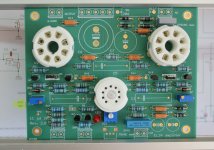
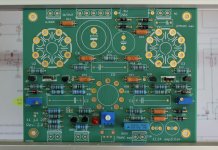
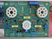
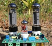
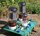
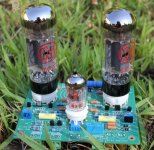
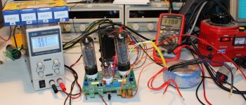
Now the amplifier is finished (only one power supply CRC capacitor is missing but that is not a problem for starting the test) and there you have photos with three different push-pull of output tubes : EL34, 6L6, and 6CA7 (the US version of EL34)...
So now I can test the amplifier, that is why I send the photos before I burn the board
Cheers,
Marc
Attachments
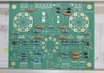
They didn't burn
I have started the tests and the amplifier sound very good like the EL84 Baby Huey but with more power of course, it has a very tight control of the loudspeaker and give very good bass even with a small speaker (I am sorry if I can't explain it very well but English is not my first language).
When I started the test I found that the bias was too high with more than 2 V on the 10 ohms cathode resistors which mean more than 200 mA and the max spec for the EL34 is 150 mA
When I try to reduce the bias with the trimmer it didn't change ! I measured -3 V on the grid instead of -16 V ? Therefor I checked all the -50 V circuitry and everything was OK ? I finally found the mistake : the trimmer and the test point were switched, that mean that when you change the adjustment on the right trimmer you must check on the left test point
After I had found that I could correct the bias to 90 mA for both tubes... Nothing to worry about or to change on the PCB, but just something to remember... I have also adjusted the balance between the two input triodes with less than 1 V difference between their plates at 160 V. No problem with the MOSFET they are not warm.
For the test I have used some old EL34 and they survived to the high bias without any problem. Now I have to build the second channel...
Cheers,
Marc
Attachments
- Home
- Amplifiers
- Tubes / Valves
- EL84 Amp - Baby Huey