Gathering parts for BH - 1st question (Picture)
I have built the sub-assemblies for the BH amplifier. I'm making it 2 monoblocks with (I think) beefy CLCR power supplies. I've scouring this 152page thread for helpful tips.
I have a question about the PS for the CCS at the input tube. The schematic shows the positive ground is supposed to go to "0V at ECC803S". Does this mean grounded near the input tube? Grounded on the CCS board? Likewise with the CCS itself. Where are these supposed to ground? Surely they connect to other grounds indirectly.
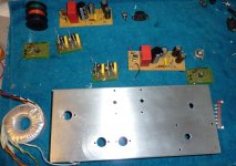
I am using the schematic on the original pages. Picture shows one aluminum chassis, toroidal PT, PS board and small Bias and CCS boards.
I have no Vol pot so will ground input jack with 100K R.
Thanks, cheers
Peter
I have built the sub-assemblies for the BH amplifier. I'm making it 2 monoblocks with (I think) beefy CLCR power supplies. I've scouring this 152page thread for helpful tips.
I have a question about the PS for the CCS at the input tube. The schematic shows the positive ground is supposed to go to "0V at ECC803S". Does this mean grounded near the input tube? Grounded on the CCS board? Likewise with the CCS itself. Where are these supposed to ground? Surely they connect to other grounds indirectly.
I am using the schematic on the original pages. Picture shows one aluminum chassis, toroidal PT, PS board and small Bias and CCS boards.
I have no Vol pot so will ground input jack with 100K R.
Thanks, cheers
Peter
Attachments
Last edited:
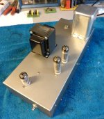
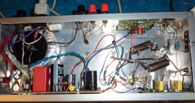
Here's one of the BH monoblock amplifiers - just completed and tested. Triode Z-565 OPTs. Antek power tranny. The silver box on top is a Stancor 5Hy choke from 1948 Scott amp.
Sounds very good. 325VDC B+
Peter
Sounds very good. 325VDC B+
Peter
Attachments
CCS testing.
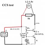
Hi all, Is the correct test for the constant current sources as per the attached drawing? Sorry to bother you with such a basic question but mine don't seem to be stable in relation to supply voltage variation so I must be doing something wrong. Thanks.
Hi all, Is the correct test for the constant current sources as per the attached drawing? Sorry to bother you with such a basic question but mine don't seem to be stable in relation to supply voltage variation so I must be doing something wrong. Thanks.
Attachments
8BQ5
Hello,
I am newbie here and I have quad set of 8BQ5 around, which are the 8v version of 6BQ5. my question is,
1) is that ok to substittue 8BQ5 in the place of el84?
2) if my power transformer doesn't have 8v, can i use 6.3v, rectify into DC and supply the heater of these tube?
thanks.
Henry
Hello,
I am newbie here and I have quad set of 8BQ5 around, which are the 8v version of 6BQ5. my question is,
1) is that ok to substittue 8BQ5 in the place of el84?
2) if my power transformer doesn't have 8v, can i use 6.3v, rectify into DC and supply the heater of these tube?
thanks.
Henry
1. Yes.
2. Yes, so long as the transformer has enough current capability. You may need to use series resistors to trim the voltage.
I have heard of people simply plugging in 8BQ5 in place of 6BQ5; however I can't comment on the effects on SQ or tube longevity.
Perhaps some forum members who have tried direct substitution would like to comment.
")
When I built my pair of BH monoblocks they sounded fantastic and still do. But while looking underneath months after the build, I discovered I had put an 18 ohm resistor in the shunt position, not 18K. (The 18 ohm Rs were around for the Bias blocks). So switched it to 18K. I think it sounded a bit better with the 18ohm, which is obviously too low, and surprised it didn't cause an audible problem. Have people tried Rs much lower than 16K, as specified for the cross channel shunt? Maybe a 1K?
Pete
Pete
Peter,
You can set that resistor to suit, I am actually running 13K in the latest build.
With 18 Ohms you would be getting the self balancing action of the BH scheme but not the shunt feedback benefits. The value you end up with will depend on if you have global feedback connected or not.
With 13K I found I did not need any global feedback. The slightly lower (than 18K I though improved stereo imaging).
Cheers,
Ian
Thanks very much for that info. I do have feedback on these amplifiers - the 12Kohm R called for in the schematic. If I tried it without feedback, I would ground the 1Kohm R from the bottom input tube grid (also as per posted schematic). Will give 13K or 12K a try.
all best, cheers
all best, cheers
Hello everybody
I have build a PCL86 push-pull amp. following the Yves Montagnon schematic and it sound really well but I've a power transformer wiyh too much output voltage, 275AC, using a Mosfet regulator is easy to obtein the 245DC recomended but the problem is heath, the mosfet is working at arround 70ºC. I would like to try your schematic with higher voltage, 320DC but I need some advise in order to fix the current adequate to the PCL86, I'm estimating arroun 25 ma. Which value would you recomend? And relating to grids working point, should it be arround -6,5V?
Thanks for your help
Fems,
I am assuming you are wanting to put the CCS blocks in the ECL86 cathodes.
The current is set by the lower resistor in those blocks.
I recommended
16 Ohms to give about 40mA
18 Ohms to give about 36mA
For 320V you would not want the ECL86 pentode sections to be idling at more than say 35 mA
22 Ohms would give about 30 mA, try that, although I would not be really fussed about using the 18R for 36mA. Want to spit the difference? Use 2 x 39 Ohms in parallel for 19.5 Ohms for around 33-34 mA.
I also would not be fussed about the MOSFET at a case temp of 70 degrees C. In the day job I put 90 degrees C thermal switches on safety critical MOSFETs. (MOSFETS to deliver 100A 60 uS pulses into Laser Diode Arrays to Optically Pump a Nd:YAG Laser Slab, those laser diode arrays, 2 off per laser, are around US$25,000 each so I designed in a lot of protection around their driving circuits).
Cheers,
Ian
2 questions about this amp
Hi,
I`am thinking about building the Baby Huey amp.
But I have two questions about it:
1. Can I use a ECC83 instead the ECC803s?
2. At wich Input level the amp reaches the full level, or in other words, what is the voltage amplification of the amp?
Best regards
Chris
Hi,
I`am thinking about building the Baby Huey amp.
But I have two questions about it:
1. Can I use a ECC83 instead the ECC803s?
2. At wich Input level the amp reaches the full level, or in other words, what is the voltage amplification of the amp?
Best regards
Chris
1. Can I use a ECC83 instead the ECC803s?
Initially I used the JJ 803s in my build but swapped them for the Sovtek 12AX7-LPS (Spiral Filament) then the Mullard ECC83, currently using telefunkens
Bias circuit
thanks for answering one of my questions.
I tried to understand the circuit, an so another question is appears to me.
The circuit for biasing the EL84 is a constant current source with approx. 40mA!
Why a constant current source is used for biasing? I would expect a constant voltage source to do this?
Cheers,
Chris
- Home
- Amplifiers
- Tubes / Valves
- EL84 Amp - Baby Huey