12AX7 has essentially no glow
IIRC my Sovtek 12AX7s had very little glow, (never used Genelex) but after a while they should feel warm to the touch. Might be good to check heater voltage under load as you have longer than usual heater cables. 10% either side of 6.3Vac will work.
As ArthurDK suggests, check you haven't wired the 12AX7s for 12.6Vac
Voltages : EL84 >> pin 7: 311V
12AX7>> pin 1: 301 V, pin 6: 301 V
In my build I got similar voltages to you, mine didn't work either
")
I replaced the ccs's with a resistor. A backward step maybe but established rest of build was good. (Sweet music was heard
). Checking out the ccs showed a simple wiring error.The black umbilical feeding the monoblock is giving 17V to the CCS
Needs to be a negative supply. Once this is confirmed you can check out the ccs. Could you post a link to the power supply schematic you're following to get your negative supply.
Nice build by the way, congrats
.
Last edited:
Thanks everyone
I'm presently at work but will have a go at looking once again at the heater supply and the CCS when I get home tonight. I'll post some more voltages and perhaps draw a wiring diagram since it is hard to see from the photo's what is going on. I'm feel I'm close yet oh so far...
I'm presently at work but will have a go at looking once again at the heater supply and the CCS when I get home tonight. I'll post some more voltages and perhaps draw a wiring diagram since it is hard to see from the photo's what is going on. I'm feel I'm close yet oh so far...
GOT IT WORKING!!!
I finally had time last night and after searching this thread realized that I had to look at the CCS and ground the "0V at E0833S" point which would then create a reference for this ‘floating’ supply to then have it’s output assume a negative potential. After I did this then I got my negative voltage. Bingo!!
I got really excited & took a chance and hooked up everything and played some CD's to see if it worked and yes it did. I listened for about 45 minutes before I called it a night but with only a crappy CD player it did start to open up after about a half hour. I'm mostly a vinyl person but I did like what I heard from the CD player very very much.
With this build I used a 6.3V taps from the transformer to power the CCS even though the schematic calls for 5V ( please click on Soonerorlater 's wiki reference in his above post). This gave -18V and the references I see in this thread call for approx -13V to -15V. Should I install a voltage divider to take the voltage feeding the CCS down to 5 V? or does it matter?
Thank you Gingertube, Soonerorlater, ArthurDK and everyone else with associated this thread.
I finally had time last night and after searching this thread realized that I had to look at the CCS and ground the "0V at E0833S" point which would then create a reference for this ‘floating’ supply to then have it’s output assume a negative potential. After I did this then I got my negative voltage. Bingo!!
Typical, you do the "hard" stuff getting your ccs board constructed right then forget to hook up one wire - did the same
From Gingertube in post 5 ,
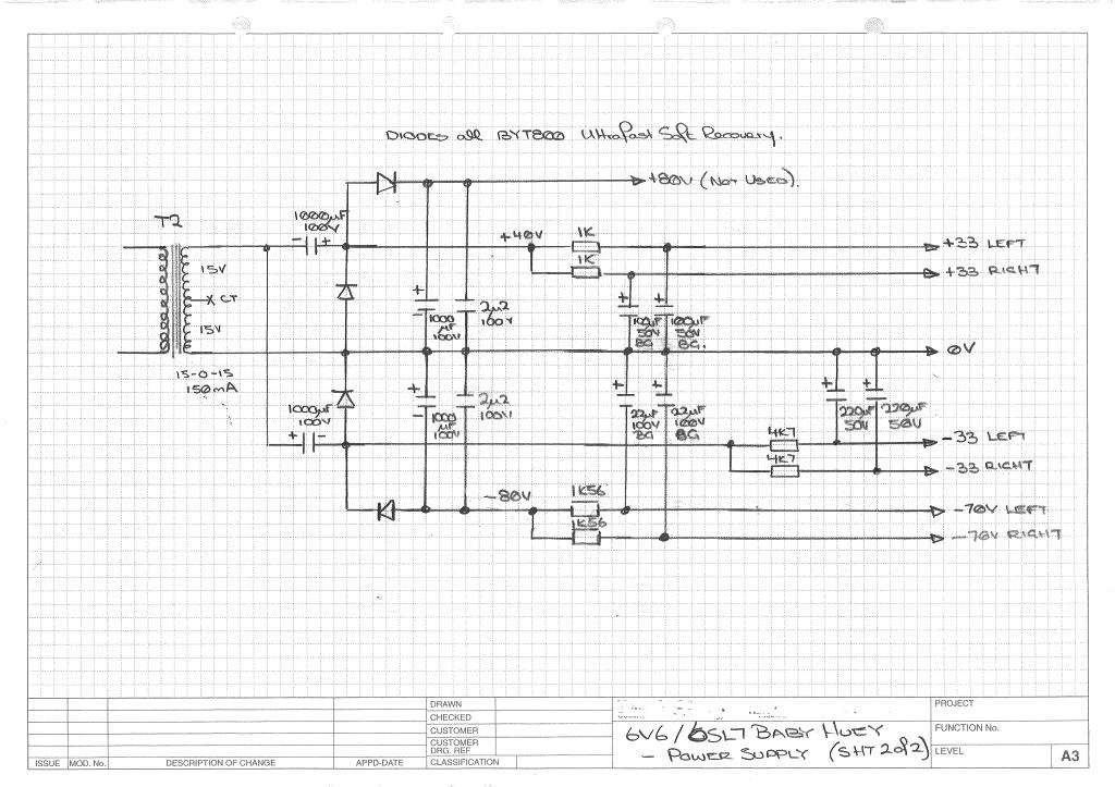
2) If you don't have a separate 5V winding to generate the -12 to -13V supply for the diffamp CCS then use what ever low voltage winding you have. The voltage isn't critical - anywhere between about -7 and -30 would be OK. You may have to adjust the 1K6 and 1K values in the current source to keep LED current at around 2 to 5 mA.
Spare 6.3Vac used ?
From Gingertubes in post 5
Last edited:
Sorry, everything off the 15V Tx. For the 6V6/SL7 version.
http://www.diyaudio.com/forums/atta...12468-el84-amp-baby-huey-babyhuey_6v6_ps2.jpg
http://www.diyaudio.com/forums/atta...12468-el84-amp-baby-huey-babyhuey_6v6_ps2.jpg
Sorry, everything off the 15V Tx.
Thanks Golana, I too have gathered together most of the parts for the 6SL7/6V6 baby huey ( sockets, valves, transformers ) and hope to start the build soon. I believe the 6SL7/6V6 version is worthy of it's own thread.
Just to clarify, T2 in Gingertubes schematic is 15-0-15 with an unused centre tap. To me this means two 15V secondaries connected in series to give 30V end to end. A dedicated transformer seems the easier path.
Your link is sht 2 of 2, could you post a link to sht 1 of 2 so we can see which version you would like to build.
Last edited:
Looks like it's from post 1358
http://www.diyaudio.com/forums/tubes-valves/72536-el84-amp-baby-huey-136.html#post3488845
http://www.diyaudio.com/forums/tubes-valves/72536-el84-amp-baby-huey-136.html#post3488845
Last edited:
HI all,
I love the sound of my 6v6 version but....I've been wondering about a 6550 variant. Any thoughts about how you would implement it? I image I would need a stepup transformer on the input to get sufficient voltage swing to drive the 6550 grids.
Any thoughts?
Andrew
I love the sound of my 6v6 version but....I've been wondering about a 6550 variant. Any thoughts about how you would implement it? I image I would need a stepup transformer on the input to get sufficient voltage swing to drive the 6550 grids.
Any thoughts?
Andrew
Have thought about a "bigger" Baby to the extent of buying a pair of Hammond 1650NA trannies (Raa = 4K3) for parallel push pull EL84 or a pair of EL34.
Also bought a pair of Hammond 1650PA (Raa = 6K6) for a pair of KT88 or 6550.
Both are on my "one of these days" list.
I would use a circuit very much like that at post #604 but add a common cathode gain stage tacked on the front. The BH definitely appreciates a low drive impedance so adding a stage on the front to give a little extra gain and buffer the impedance would be good.
An alternative is to try a cascode or pentode diffamp as the BH input stage. That will give you sufficient gain.
Cheers,
Ian
Global Feedback if used would go where it currently does.
AJT's scheme is what I would use too, Common Cathode Input Stage driving a Volume Pot which then goes into the "standard" BH. I'd probaly use a 50K pot.
Of the Signal Voltage going into the BH part you have to remember that the cathodes of the diff amp are sitting at 1/2 that signal voltage, so input grid to cathode you only see 1/2 the drive voltage. It is possible that you may still overdrive it, It is something you would need to check.
If that becomes a problem I would abandon that method and use the BH scheme "as is" but with the triode diff amp front end replaced with a cascode diffamp or a pentode diffamp to get the extra gain required. Both are likely to sound quite different, maybe better, maybe not. The low current requirement imposed by the BH anode to anode feedback scheme would probably tempt me into trying EF86 or 6BR7 pentode diff amp first.
If you wanted to go cascode triode stages instead then I'd have to have a bit of a think about a suitable tube. 12AX7 are crap in cascode. You need something with reasonable gm but at the same low operating current (approx 700 uA).
Cheers,
Ian
Last edited:
Personally, I would like to stick to octals. I'm imagining 6550 driven by 6SL7s driven by a Common Cathode Input Stage...say a 6J5 or even a 76? Afterall you only need gain of about 4x drive into the 6SL7's to swing some serious voltage into the 6550's....or am I missing something....
Overall, the input stage needs to no more complex than the current 6v6 or EL84 design in my opinion
Overall, the input stage needs to no more complex than the current 6v6 or EL84 design in my opinion
- Home
- Amplifiers
- Tubes / Valves
- EL84 Amp - Baby Huey