How are you getting all those even harmonics? It's a PP design. Looks to me like something's way out of balance here. I was never really impressed with this design with its overly (and unnecessarily) complicated lNFB scheme.Distortion measurements
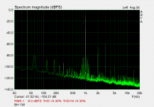
I've finished one channel of my EL84 Baby Huey and made some distortion measurements without any global feedback.
View attachment 1030838
I suppose it's not too bad given the 0.13% suggested by LTSpice. I was able to reduce the THD by 0.08% to the 0.19% you can see by adjusting R5 on the cathodes of V1A and V1B.
Has anyone else done any measurements? Listening tests will have to wait until I have the second channel built.
Good question. I'll investigate. With a gain of only 23dB there's not much room for additional, global negative feedback, even it you wanted it.
I'm using a toroidal OPT with a bias servo.
The distortion profile is pretty much as predicted by LTSpice. I'd still like to understand why the result is less than optimum even with the existing feedback.
I'm using a toroidal OPT with a bias servo.
The distortion profile is pretty much as predicted by LTSpice. I'd still like to understand why the result is less than optimum even with the existing feedback.
Attachments
Hello, Can I ask, did you buy the U082s direct from sowter ?If it must be Sowter I would go with these, just to be safe: SOWTER TYPE U082
The reason why I went for 23% DL taps is that old Mullard says there's basically no need to exceed 20% like DL, plus can be squeezed more power, plus shunt feedback should linearize the response towards g1=0 (that is indeed more linear with 43% rather than 23%).
There will be less need to go into AB2 with 23% DL, but screen stoppers will need IMHO to be higher than with 43% DL, because the plates go lower in voltage, so the dV is higher with 23% DL, and so secondary emission, and screens need to be protected more.
Please note that I kept 8k Raa even with 23% DL, but datasheet suggests 6.6k in this case (it goes more on the right of the pentodes' knee, where curves are more equally spaced). Again, I went with 8k because of shunt feedback. Without it I would probably have gone with 6k6.
Adjusting trimpots for minimum distortion
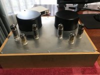
I finally have my EL84 Baby-Huey in a temporary box and in my system covering 1kHz on up. At some point I’ll make a nice box from a local hardwood. I also have to get the top plate re-made after the guy who attached the M5 studs to the underside didn’t quite get them in exactly the right places and I had to take to the transformer holes with a file. I hate metalwork!
I’m using balanced inputs with signal to the 12AX7 grids. The amp sounds great! I’m not using any global negative feedback.
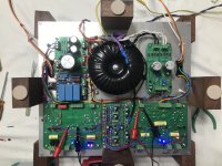
For various reasons I decided to design my own PCBs:
Now to my question about adjustment of the pot between the cathodes of V1a and V1b.
Minimum distortion is at the extremities of the pots.
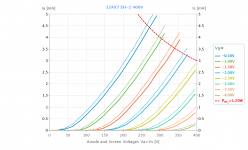
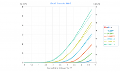
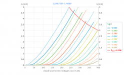
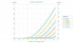
I’m using a pair of new 12AX7EHs that were purchased as matching. The gains are pretty close but not much else as you can see

If I were to get 12AX7s that were better matched and closer to spec, could I reduce distortion further?
Having just written all this it occurs to me that I should re-read the section in Morgan Jones' book on distortion in long-tailed pairs. Unfortunately, it's currently underneath an upside-down, very heavy SE amp I'm repairing for someone!
I finally have my EL84 Baby-Huey in a temporary box and in my system covering 1kHz on up. At some point I’ll make a nice box from a local hardwood. I also have to get the top plate re-made after the guy who attached the M5 studs to the underside didn’t quite get them in exactly the right places and I had to take to the transformer holes with a file. I hate metalwork!
I’m using balanced inputs with signal to the 12AX7 grids. The amp sounds great! I’m not using any global negative feedback.
For various reasons I decided to design my own PCBs:
- I’m using a bias servo so no trim-pots etc for biasing required. I wanted to use PCB-mounted sockets for that but I’ve had to temporarily solder bias servo wires directly to the PCB because the plugs and sockets I want are out of stock. Delivery keeps getting put back with the latest delivery estimate being October.
- I wanted all power supply components off-board
- I wanted room to stick a line input transformer to the boards if I decide to go single-ended input with feedback.
- I wanted proper test points on the board
Now to my question about adjustment of the pot between the cathodes of V1a and V1b.
Minimum distortion is at the extremities of the pots.
I’m using a pair of new 12AX7EHs that were purchased as matching. The gains are pretty close but not much else as you can see
If I were to get 12AX7s that were better matched and closer to spec, could I reduce distortion further?
Having just written all this it occurs to me that I should re-read the section in Morgan Jones' book on distortion in long-tailed pairs. Unfortunately, it's currently underneath an upside-down, very heavy SE amp I'm repairing for someone!
Attachments
Yes. Just look at the current flowing in the two triodes of V1. One is 1.5 mA and the other 0.9. This, across the two 220k loads, causes a drop of 330V (do you have any voltage left?) and on the other side 198V. Both values are higher than what should be. Are you sure the CCS under the LTPI is set properly?If I were to get 12AX7s that were better matched and closer to spec, could I reduce distortion further?
When I've finished the repair job I'm working on for a friend I'll take the BH out of my system and do some measurements. Those 12AX7 measurements I posted are not from the amp but from my uTracer. The triodes in one of the EH 12AX7s are reasonably close. Not so the other one.
Attachments
Hello everyone!
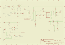
I have been following this thread for quite long time, along with the EL34 BH and at some point I have decided to build the EL84 version. The schematic I have worked with is the version attached below.
I have powered it up, with the ECC83 plugged in and no power stage tubes.
The B+ I have is 332-333Vdc
The filaments are 6.3DC
Current source voltage is -68Vdc , with 1.15Vdc measured across R4 which to me comes up to 1.69-1.7mA.
The positive voltage for the MOSFET drive is +68Vdc.
Now the problem I have is that I am trying to balance the voltages on the anodes of the ECC83 but the setting is not stable.
I can manage to set it to Zero, but it varies in time from -1Vdc to +1Vdc. Is that something normal, or should I check anything. The voltage on the anodes of the ECC83 is aprox 162Vdc.
I am using a 12AX7 EH balanced tube.
Kind regards.
Hi fizildiken,
Unfortunately the Gerbers for the Baby Huey EL84 PCB group buy was not made available publicly. However, if you are able to do such things, @tristanc kindly posted the simulation files, layout and gerbers for his adaptation of the EL34 Baby Huey. Perhaps you could remake it into an EL84 PCB. Note that he chose to have one PCB for both channels, rather than one per channel.
You can find the github link here: https://www.diyaudio.com/community/...og-an-engineers-baby-huey.383564/post-6971542 in his thread on his work and amplifier build.
If this route is not feasible you could post WTB advertisement in the appropriate thread - I am sure there are some unused PCB’s sitting in someone’s closet. I may even have some.

Merhaba Francois,Merhaba fizildiken,
Ne yazık ki Baby Huey EL84 PCB grubu satın alımı için Gerberler halka açıklanmadı. Ancak, eğer böyle şeyler yapabiliyorsanız, @tristanc, EL34 Baby Huey uyarlaması için simülasyon dosyalarını, düzeni ve gerberleri gönderdi. Belki onu bir EL84 PCB'ye dönüştürebilirsin. Kanal başına bir PCB yerine her iki kanal için bir PCB'ye sahip olmayı seçtiğine dikkat edin.
Github bağlantısını burada bulabilirsiniz: https://www.diyaudio.com/community/...og-an-engineers-baby-huey.383564/post-6971542 kendi dizisinde çalışmaları ve amplifikatör yapısı üzerine.
Bu rota uygun değilse, WTB reklamını uygun başlığa gönderebilirsiniz - Eminim birinin dolabında kullanılmayan bazı PCB'ler vardır. Hatta biraz alabilirim.
I like your sticker picture. The picture is from Cappadocia. I live in that area.
Zintolo has a set for sale
https://www.diyaudio.com/community/...-and-non-populated-bonus.392311/#post-7181879
Edit, I didn't see the el84 had sold, you might be able to use the other boards with an adapter
https://www.diyaudio.com/community/...-and-non-populated-bonus.392311/#post-7181879
Edit, I didn't see the el84 had sold, you might be able to use the other boards with an adapter
Last edited:
Very nice. Can you share your full schematic - keen to know what you used on the power supply side. And would you be willing to share your layout files? The PCB looks great.Just wanted to share with you my joy
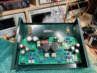
My 6P14P-EV Baby Huey is getting a real "home".
Thanks to everyone contributing.
- Home
- Amplifiers
- Tubes / Valves
- EL84 Amp - Baby Huey