Hi,
BTW, which tube are biased at 45mAdc ? I thought the EL34/6CA7 were bias at 100mA/valve so 200mAdc (320mA AC per channel). Is the bias current requirement the same for fixed bias vs cathode bias ? I’m used to sizing PSU for cathode bias PP and SE. This will be my first fixed bias PP.
BR
Eric
BTW, which tube are biased at 45mAdc ? I thought the EL34/6CA7 were bias at 100mA/valve so 200mAdc (320mA AC per channel). Is the bias current requirement the same for fixed bias vs cathode bias ? I’m used to sizing PSU for cathode bias PP and SE. This will be my first fixed bias PP.
BR
Eric
Hi spaceistheplace,
The standing current is something you determine along with your power output. You can run the tubes conservatively (and have excellent sound quality), or you can wind them out as P-P class A, or for full power. Your peak current demands are like peak current in the music signal. You only need design for the average level and not the peaks added together. Keep in mind that the energy storage varies as V^2 * C. That quickly adds up to a lot of energy storage. So your current requirements are much lower than you might think, as is the required capacitance. Too high a capacitance doesn't do you any favors. You aren't using your amplifier is a disco pounder, so you don't want the extra inrush current or hot switching current in the rectifiers or filter capacitors. This also increases supply noise a fair amount, so if you don't need it, don't design for it. That is why many larger tube amplifiers used 40 uF capacitors very effectively. They didn't need anything larger.
Hi Fred,
No issues from me at all. I've zero problems with people who restore their amplifiers to some state resembling the original circuits.")
-Chris
The standing current is something you determine along with your power output. You can run the tubes conservatively (and have excellent sound quality), or you can wind them out as P-P class A, or for full power. Your peak current demands are like peak current in the music signal. You only need design for the average level and not the peaks added together. Keep in mind that the energy storage varies as V^2 * C. That quickly adds up to a lot of energy storage. So your current requirements are much lower than you might think, as is the required capacitance. Too high a capacitance doesn't do you any favors. You aren't using your amplifier is a disco pounder, so you don't want the extra inrush current or hot switching current in the rectifiers or filter capacitors. This also increases supply noise a fair amount, so if you don't need it, don't design for it. That is why many larger tube amplifiers used 40 uF capacitors very effectively. They didn't need anything larger.
Hi Fred,
No issues from me at all. I've zero problems with people who restore their amplifiers to some state resembling the original circuits.
-Chris
Hi Eric,Hi,
BTW, which tube are biased at 45mAdc ? I thought the EL34/6CA7 were bias at 100mA/valve so 200mAdc (320mA AC per channel). Is the bias current requirement the same for fixed bias vs cathode bias ? I’m used to sizing PSU for cathode bias PP and SE. This will be my first fixed bias PP.
BR
Eric
This was simply an example to illustrate how to determine the current capacity of a PT.
This is a class AB amp, the bias current is the idle current. You can certainly bias at 100mA at idle, but there is one important factor was not discussed at all - the OT.
Since I have the Toroidy EL34 OT which as 6600 impedance. 100mA * 6600 implies B+ of 660V!!! So, the tube will be dissipating 66W at idle.
Take a look at the 6CA7 datasheet. The max plate dissipation is only 25W. So, I don't think the tube will last.
In order to "safely" bias at 100mA per tube, you probably need an OT with impedance no more than 2000 ohm. This in turn implies the B+ is no more than 200V.
See, there can be many parameters at the beginning, but once some values are fixed (e.g 6CA7 tube and Toroidy EL34 OT), the remaining options will be greatly reduced/limited. In my example with the Toroidy OT, the tube will be idling at around 13W - approx 50% of the max dissipation, the tube life should be decent.
IMHO, there is no perfect configuration. Marc has published his proven configurations. So, one can follow his path, or be a little advantageous to try some different
At the end, there will be compromises. The decision is usually determined by one's preferences and/or parts already on hand.
Have fun!!
Hi Eric,
Too late to edit, kind of stupid to drag the OT impedance into the discussion Low glucose level really hinder the brain, happened more often than I like, sigh.
The plate dissipation is essentially the voltage across the tube * the plate current. With a 250V B+, the tube will be at a little lower than the max dissipation (250V * 100mA = 25W), roughly, due to the OT. For the tube longevity, we don't want to idle at max dissipation. Also, these tubes love higher voltage. I personally prefer at least 350V. Hence, the 45mA bias.
Keep in mind, each tube can swing higher than the idle current in class AB. Kind of like the First Watt F5 leaving class A, one device will have to eat all the load. That's why you don't want the device to be biased at the limit.
To size the PT, I usually use this calculation for one channel:
idle current * 3
regardless of fixed bias or cathode bias.
SE is pure class A, the bias current is the max current through the tube, unlike class AB. Hence, the bias current is what you use to calculate the PT.
Too late to edit, kind of stupid to drag the OT impedance into the discussion
Low glucose level really hinder the brain, happened more often than I like, sigh.The plate dissipation is essentially the voltage across the tube * the plate current. With a 250V B+, the tube will be at a little lower than the max dissipation (250V * 100mA = 25W), roughly, due to the OT. For the tube longevity, we don't want to idle at max dissipation. Also, these tubes love higher voltage. I personally prefer at least 350V. Hence, the 45mA bias.
Keep in mind, each tube can swing higher than the idle current in class AB. Kind of like the First Watt F5 leaving class A, one device will have to eat all the load. That's why you don't want the device to be biased at the limit.
To size the PT, I usually use this calculation for one channel:
idle current * 3
regardless of fixed bias or cathode bias.
SE is pure class A, the bias current is the max current through the tube, unlike class AB. Hence, the bias current is what you use to calculate the PT.
Need help...
Hi,
I’ve just finished building the amp and after power on and before proceeding to adjust the amp, the led start flashing. Is this normal behavior?
The voltage across C5 start at 420 volts and then drops progressively to below 385v but with a varying value. It does not ends at a fixed value. Any clue?
The transformer is stated to be at 275v but I’ve measured it to be around 300v more or less. How can I drop the B+ to a suitable value? Change R27 to a higher ohm rating? Max voltage rating for caps is 400v. I’m worried about safety with the voltages being so close to max tolerance of the caps.
I have checked part list and I feel confident that all parts are in the correct place and in the intended orientation...
Please help...:sorry
Jorge
Last edited:
Hi
First thing to do before powering up a tube amp; if your OPT are connected make sure you connect a load, ex 4-8 ohm.
With your transformer I would make sure C5-C7 are rated above 450Vdc.
R27 might be used to mesure total bias or something, not sure if you should change the value but you are correct therefore increasing the value will drop your B+
You could also replace R27 by a choke, this will drop your B+ and normally makes an amp even quieter.
BR
Eric
Hi Jorge,
You can also use a power resistor between the first large filter capacitor where it will drop a lot of voltage with little heat. It works by limiting the peak currents on start-up and the hot switching currents as well. This immediately reduces rectifier noise.
Adding a choke is a double edged sword. Do it wrong and it picks up noise or can couple to the power transformer and make your ripple worse. It also will radiate like a transformer. So therefore you have to treat the choke as you would a transformer. The calculations are more important too. You have to make sure the current never drops to zero with a choke.
-Chris
NO - the LED flashing is not normal behaviour. It should be on steady.I’ve just finished building the amp and after power on and before proceeding to adjust the amp, the led start flashing. Is this normal behavior?
Are you sure you dod'nt get a flashing led supplied by mistake? I can't see any real way for the LED to flash otherwise.
Cheers,
Ian
Flashing LED
Hi Ian,
I ordered the one that it is stated in the BOM but there is an error somewhere as the part number is ok but the led is a three pin one nor the usual two pin. I used two I had on hand, I´m going to change it to a different model this evening and will report back.
Thanks for the answers, I appreciate....
Regards,
Jorge
Hi Jorg,
You are right, there is an error in the BOM I don't know why I indicated this LED ?
Any cheap red LED will be OK, the important characteristic is the forward voltage of 1.7 V, you can use this model by exemple : 630-HLMP-4700-C0002 it is available from Mouser : HLMP-4700-C0002 Broadcom / Avago | Mouser France
Sorry for this mistake !
Best regards,
Marc
You are right, there is an error in the BOM
I don't know why I indicated this LED ? Any cheap red LED will be OK, the important characteristic is the forward voltage of 1.7 V, you can use this model by exemple : 630-HLMP-4700-C0002 it is available from Mouser : HLMP-4700-C0002 Broadcom / Avago | Mouser France
Sorry for this mistake !
Best regards,
Marc
No way
Hi,
It’s impossible to adjust bias. The bias pots do nothing neither side.
The voltage across C5 is around 385v but not steady and starts at 415v more or less...
Both channels behave identical. Led flashing and a pulsating sound trough the speakers. So I have done the same error on both boards or is a problem before the boards.
Help...
Jorge
Hi Jorge,
Don't forget that you must read the bias voltage on the opposite side of the trimmer, see last page of the "Building recommendations..." !
It is normal that the high voltage decrease from 415 V to 385 V after power up because when the heater are cold there is no current in the tubes but when they are warm the load consumption reduce the voltage...
LED flashing is not normal, are you using 50 V AC on the bias power input ?
Good night,
Marc
Attachments
Hi Marc,
I know that the bias voltage is measured in the opposite side but as I stated before, the pots do nothing.
The bias voltage is 50v.
Jorge
I know that the bias voltage is measured in the opposite side but as I stated before, the pots do nothing.
The bias voltage is 50v.
Jorge
Attachments
Last edited:
Hi jorge,
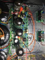
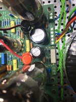
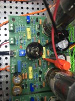
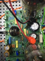
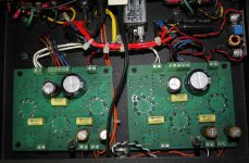
Did you find the reason for the flashing LED and the bias problem ? I think that you should look to the negative power supply since these two circuits are powered by the minus 70 V... You can check that you didn't swap the two 50 V AC connections, because even if it is AC and can be connected in both directions, when you connect one side of the transformer to one contact, YOU MUST CONNECT THE SECOND BOARD IN THE SAME WAY because one of these input is connected to GND and if you cross them, you will create a short circuit I am thinking about that because I see on yours photos that the 50 V connection is twisted, which is good to avoid noise, but check on the input connector that you don't have 0 ohms ? If this is the case change the connection and check again...
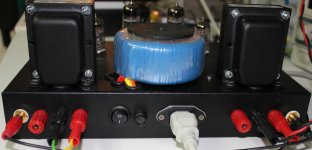
In the mean time I have finally en enclosed amplifier based on the EL84 version of the Baby Huey
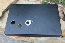
May be you remember the problem I had in the past with the steel Hammond chassis when I wanted to make the holes for the tubes (see first photo), but during all these discussion on Internet, I meet a nice guide living also on the French Riviera not too far from me, who helped me by doing this hard mechanical work with the chassis ! As you can see on the photos of the finished amplifier my previous mistake is nearly invisible I have been listening the amplifier and I am very happy with the sound, of course it is less powerful than the EL34 version, about 10 W, but the music is very clear and not agressive at all, you can listen during several hours without problem.
Now we will work on a new cabinet for the EL34 version !
I will publish the photos as soon it is finished...
Cheers,
Marc
Did you find the reason for the flashing LED and the bias problem ? I think that you should look to the negative power supply since these two circuits are powered by the minus 70 V... You can check that you didn't swap the two 50 V AC connections, because even if it is AC and can be connected in both directions, when you connect one side of the transformer to one contact, YOU MUST CONNECT THE SECOND BOARD IN THE SAME WAY because one of these input is connected to GND and if you cross them, you will create a short circuit
I am thinking about that because I see on yours photos that the 50 V connection is twisted, which is good to avoid noise, but check on the input connector that you don't have 0 ohms ? If this is the case change the connection and check again...In the mean time I have finally en enclosed amplifier based on the EL84 version of the Baby Huey
May be you remember the problem I had in the past with the steel Hammond chassis when I wanted to make the holes for the tubes (see first photo), but during all these discussion on Internet, I meet a nice guide living also on the French Riviera not too far from me, who helped me by doing this hard mechanical work with the chassis ! As you can see on the photos of the finished amplifier my previous mistake is nearly invisible
I have been listening the amplifier and I am very happy with the sound, of course it is less powerful than the EL34 version, about 10 W, but the music is very clear and not agressive at all, you can listen during several hours without problem.Now we will work on a new cabinet for the EL34 version !
I will publish the photos as soon it is finished...
Cheers,
Marc
Attachments

Flashing LED & Bias
Hi Marc,
I will checking this when I arrive at home. I am thinking that could be possible but I feel it´s not the problem because in the troubleshooting process I disconnected one channel to see if I made a mistake only in one board or in both. I checked both channels boards alone (like in a mono config) and the led flashed. One thing I thought was the connections of the output transformer because if I disconnect it, the led does not flash but it´s impossible to bias though. I´ve been in contact with Toroidy and after some voltages cheking, we agreed that the problem was not the transformers.
I hope you are right because I am very anxious to hear the amp.
Regards,
Jorge
Still stuck
Hi all...
I’m afraid to confirm that I’m still stuck with the flashing leds, pulsating sound at speakers and no way to bias the amplifier.
I checked the cables for bias and I’m sure they are connected as told by Marc. The voltage is around 48volts, the resistance at the bias input is around 10 ohms. The ac input is around 275.
The voltages are dancing, non steady.
I’m desperate....
Regards
Jorge
Last edited:
- Home
- Amplifiers
- Tubes / Valves
- EL84 Amp - Baby Huey