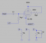
I have a pair of EL156 and would like to build a SE triode mode and fixed bias with it as a prototype for studying.
According to datasheet, I take:
Ua: 500V
Ug2: 350V
OPT with 3.5k impedance
let's suppose I want to bias at -16V, as attached document.
- How to calculate the negative voltage needs on Vg1 for -16V bias?
- Which option(A/B/C) does cathode connect to? I think I should adopt A and I can adjust the bias by measuring the voltage of Rk, how to I calculate the value of Rk?
- how about option C? Is it necessary to have a cathode bypass capacitor?
I had been learning and searching but still not able to find a step-by-step through procedure. Great thx for any hints
Attachments
...EL156 ...fixed bias ...for studying.
- How to calculate the negative voltage needs on Vg1 for -16V bias?
- Which option(A/B/C) does cathode connect to?
Is it necessary to have a cathode bypass capacitor?
I had been learning and searching but still not able to find a step-by-step through procedure. ...
This general design process has been written-up by many authors many-many times before. I don 't know why I will beat my fingers to a pulp to re-type it again.
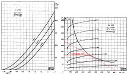
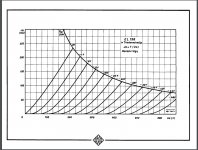
The EL156 data and its triode curves are readily available. Yes it is in German. I know almost no German. But anybody familiar with data-sheets can pick-out the key points. Perhaps you could read a lot of datasheets to know how they give information.
You don't start by assuming a grid bias-- you figure how you want the plate circuit to run, get a rough idea how much bias voltage will be needed.
If you *must* use fixed bias, the cathode is grounded and bias is applied to G1-- very basic power-amp configuration covered in many places.
For SE (class A), especially with low bias voltage expected, "whenever possible ALWAYS run self/cathode bias" (RDH4th). It self-adjusts for tube variation. It is less likely to go real bad and melt expensive tubes or transformers. With say 6080 triode the bias is half as big as the plate-cathode voltage, so self-bias is wasteful. But EL156 bias is only 5% of the total supply voltage. The "waste" is small and the gain in reliability is large.
You want to study. Build it, then try with and without a cathode bypass cap. First thing you will notice is that it takes twice as much grid voltage signal to get the same output. This is not a big problem since drive is small. Further study shows the THD is about half, and the output impedance is about double. Generally we use a cap. But it is a point to study.
Loading: you can draw load-lines until your pencil is down to a stub. Generally you pick an impedance significantly larger than the triode's plate impedance, but not so high that you exceed any voltage rating to get near the dissipation limit. (You want to be near Pdiss Max to get the most out of your expensive tubes.) The zero-bias line of El156 lies near 1K (200V, 220mA). Go 2X to 5X higher, 2K to 5K.
Your final working B+/Ik will be around rp+RL. So for 2K load, 3K; for 5K load, 6K.
To hit 50 Watts Pdiss, for 3K equivalent resistance you need 387V at 129mA; for 6K equivalent resistance you need 547V at 91mA.
As a quick-guide, power output of triode power amp is 25% of plate dissipation. So 50W plate offers about 12 Watts output.
At this point you should set theory aside and see what transformers, power and output, you can actually buy. Also filter-caps: electrolytics over 450V are expensive, and you should leave a large margin, favoring 400V or less working B+.
Choices for 15W SE OTs are limited. I *really* think, for study, from where you are now, you should breadboard a 6L6/KT66 at maybe 15 Watts dissipation (4W out). The choice of OTs at this power level is much wider (and less expensive); and you are not risking %5--$500++ tubes.
- Status
- This old topic is closed. If you want to reopen this topic, contact a moderator using the "Report Post" button.