What are “these”?Only reason I ask is that I have a number of these ….
There is nothing wrong with using output tubes in parallel arrangement. There are some advantages but also pitfalls:Only reason I ask is that I have a number of these and
In my case I would use a different PS arrangement and different opt’s.
I would not just parallel up more outputs without making the changes required to accommodate the increased demand.
- It becomes harder to balance the output tubes. Use individual biasing resistors for each tube.
- Make sure the output transformer can handle the 2x quiescent current. You will probably need to use a lower primary impedance to get the desired result, which I assume is just more output power.
- The same with the power supply, more heater and B+ current, as @6A3sUMMER explained.
- The LTP will have to drive twice the capacitance. Probably not an issue.
Last edited:
I have used parallel output tubes, and my reasons were:and why ?
1) I had the tubes (6P41S), 9 of them, and I did not want to spend any extra money on tubes.
2) I wanted at least 10W in a single ended configuration. A single tube was not enough.
It worked very well.

Thanks Eli
well, there also is the 6AL5 with 6V heater, and even cheaper
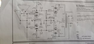
btw, for those(like me) who may have been confused about T7, it refers to 12AT7
The exstreme low cost met by your design have been impressive
I wouldnt mind a small increase in cost, without going completely wild
With such low cost the shipping alone will be a major player
And we may have custom fee etc
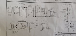
Hello Diyurselfers,
I just built the el cheapo exactly as the schematic was presented. I can't get to 6 ma on the 12at7. I triple checked everything including swapping valves etc. I have not boosted the b+ voltage yet as I want to get the t7 under control before I do. I'm posting some voltage numbers for anyone willing to help me trouble shoot.
Thanks OB
Attachments
Are you trying to get 6mA per plate on the 12AT7?Hello Diyurselfers,
I just built the el cheapo exactly as the schematic was presented. I can't get to 6 ma on the 12at7. I triple checked everything including swapping valves etc. I have not boosted the b+ voltage yet as I want to get the t7 under control before I do. I'm posting some voltage numbers for anyone willing to help me trouble shoot.
Thanks OB
You have 6.1V in the cathodes, that's too big. Something is wrong with the CCS I guess.
Last edited:
I get the values in your pic when the CCS adjust potentiometer is at ~850 ohm. The CCS current goes from ~ 1.3mA to 11mA when you adjust that pot.Are you trying to get 6mA per plate on the 12AT7?
You have 6.1V in the cathodes, that's too big. Something is wrong with the CCS I guess.
My bad! I'm looking for 30 volts which would be 3 ma per tube. 1.5 ma per plate. Yes I was thinking the ccs as well. I wonder if one (as I have two one per each channel) is not working will that prevent the other from working properly?Are you trying to get 6mA per plate on the 12AT7?
You have 6.1V in the cathodes, that's too big. Something is wrong with the CCS I guess.
No when I try to adjust the ccs the voltage across the 100 ohm resistor doesn't change. The voltage on the cathode doesn't either.I get the values in your pic when the CCS adjust potentiometer is at ~850 ohm. The CCS current goes from ~ 1.3mA to 11mA when you adjust that pot.
My bad! I'm looking for 30 volts which would be 3 ma per tube. 1.5 ma per plate. Yes I was thinking the ccs as well. I wonder if one (as I have two one per each channel) is not working will that prevent the other from working properly?
Each channel's CCS is an independent circuit, well, apart from the B- supply.
Here is a simulation that matches the real values (6mA across R8, i.e. 3mA for each plate) :
Hmmm, it could be, these are fairly specialised high voltage depletion mosfets, I would get them from a very reputable source. I typically use DigiKey. For the record, I order a lot from e-bay/Aliexpress, but not specialised components. Digikey has very decent prices for the DN2540, I just bought 10 last week. If you spend more than £33 (UK) you get free delivery.I had to order the Fets from China (ebay). I wonder if I got a bad batch?
- Home
- Amplifiers
- Tubes / Valves
- El Cheapo, builders thread