Re: Re: Marshall
I agree Miles. The 814 is a neat tube. I used to have 48 Westinghouse NIB and I threw then out during a big and long distance cross country move. A the time I really believed that I was completely done with tubes. I have been kicking myself ever since.
I cobbled together an amp with clip leads back in the early 80`s on a wooden workbench using four 814`s in P-P-P, however each pair fed a Hammond 1656 (I think) which is a 60 watt OPT. The output windings were parallelled. Used a pair of 282X Hammond power xfmers in series to make a 1400 VDC B+ supply. I used a backwards 15 watt audio OPT as a phase splitter and driver and an external SS hi-fi amp as the source of drive. This baby kept cool as a cucumber making an easy 400 watts RMS (100 watts per bottle) showing no plate color. It sounded remarkably good at 400 watts too. To listen to it I had it feeding a suitable resistive load bank to handle the power and trhen a series R to a speaker to tap off just a few watts for sonic evaluation.
These tubes seem hard to find.
I`d like to try a pair as SE triode wired. I currently have four.
Miles Prower said:
Not really. If I wanted that much power, I'd get a couple of 814's (807's DH big brother) and run them Class AB2. Getting that many VTs all pulling together will probably require a PIC-based bias circuit. There was a design out there ("The Emperor's New Amp"?) that used 4 PPP 6BQ5s, and that used coordinated integrator type bias stabilization.
I agree Miles. The 814 is a neat tube. I used to have 48 Westinghouse NIB and I threw then out during a big and long distance cross country move. A the time I really believed that I was completely done with tubes. I have been kicking myself ever since.
I cobbled together an amp with clip leads back in the early 80`s on a wooden workbench using four 814`s in P-P-P, however each pair fed a Hammond 1656 (I think) which is a 60 watt OPT. The output windings were parallelled. Used a pair of 282X Hammond power xfmers in series to make a 1400 VDC B+ supply. I used a backwards 15 watt audio OPT as a phase splitter and driver and an external SS hi-fi amp as the source of drive. This baby kept cool as a cucumber making an easy 400 watts RMS (100 watts per bottle) showing no plate color. It sounded remarkably good at 400 watts too. To listen to it I had it feeding a suitable resistive load bank to handle the power and trhen a series R to a speaker to tap off just a few watts for sonic evaluation.
These tubes seem hard to find.
I`d like to try a pair as SE triode wired. I currently have four.
tubelab.com said:
"estimated" at $42 USD.
plus UPS independently will bill you another $20 for their brokerage service.
I thought about this while I was outside mowing my lawn, and then looked up a few things when I got back inside. It has been discussed a bit already and a new thread has been spun debating the advantages of the 814 VS the 828. I have a bunch of 828's so I thought about these and came to the conclusion that neither of these tubes would be good with these transformers. Both tubes have a maximum plate current of 150 mA. Both seem to like highish plate voltages and large (10 to 16K ohm) load impedances. The Plitron transformers have a 1250 ohm impedance and the maximum working voltage is not specified, but I wouldn't try to run them at 1KV+. I am sure that a load line could be plotted with a 500 to 600 volt B+ and a 1250 ohm load, but the 150 mA maximum will be the limiting factor. I even thought of bringing out the big boys, a pair of 813's, but these have the same issues. I am not familiar with the GU-50.
It was stated that these transformers were intended for a 400 watt Marshall bass guitar amp. If that is true, then they were probably intended for use with 6 or 8 KT88's at 500 to 600 volts. Therefore this would be the easiest path to that monster amp. If 400 watts are not needed, and HiFi operation is more important than sheer power, 8X 807's doesn't sound too far fetched. Yes there will be some setup / matching / aging issues, but once they are overcome, the amp should work well and last forever. There are plenty of guitar amps out there that use 6 X KT88 to make 300 to 400 watts per channel. Other than the exploding early vintage Ampeg SVT's (6 X 6146's) they are pretty reliable.
I think that the setup / matching / aging issues would be worse in class A due to the higher dissipation. The imbalance problem associated with toroidal OPT's would be worse in class A. Some type of auto bias circuit might be a good idea.
The more I think about this, the more I think my first attempt will be screen driven class B sweep tubes. I'm thinking 4 X 6LW6's per channel. Plenty of reserve current handling capability, a good match for the 1250 ohm transformer, and the B+ voltage would be in the 500 to 600 volt range.
Now I suppose I could just wire up 6 X Electro Harmonix KT88's per channel, but I have done that before (about 15 years ago). I was intrigued by the results I got when I tried a pair of 6AV5's in screen drive about a year ago. The 6AV5's, which are smaller than a 6L6GC, were happy cranking out 80 watts which was limited by the OPT that I was using. The distortion was low without any feedback. I just got to try this again with a decent OPT.
I've been toying with the idea of PPP EL38s (they have 400V/8w g2s) - the price of the tertiary transformer (for UL) has been holding me back though. Biased hard into class B, you can make 84Ws using only a pair...
Condition 5 fixed bias
Plate 600 volts Screen: 400 volts
Grid one -ve 25.2 volts
Plate current (each valve) 30 ma (zero signal) 103 mA (max signal) Screen current (each valve) 3.4 ma (zero signal) 28.5 mA (max signal) Load plate-plate 7.5 K ohms volts in (grid-to-grid) 34.6 volts rms
Power output 84 watts
I've also been thinking of the power supply and the needs of class B - perhaps a beefy regulated supply... ah well... future project...
That should work well. Its double what I've done with 2 pairs of EL34s in triode mode into a 1885 ohm Raa PAT4006 (VDV2100).
Driving them is going to be a real issue. Might I suggest cascode diff amp (6DJ8) ala Allen Wright PPC1 but at about 4 to 5mS per side (to get enough gain) buffered by White Cathode Followers to drive the estimated 800pF of Miller capacitance of 4 807s in parallel on each side.
Thats what I use as a front end on my amp (except Series Regulated HV using a Maida Reg in lieu of a shunt "Super Reg" and MOSFET Source Follower in lieu of White Cathode Follower) to drive the 500pF of 2 EL34 per side.
I recently repaired am AMPEG bass amp (SVT3 PRO) which used a white cathode follower to drive the input capacitance of 8 high power output MOSFETs - that would be a similar load (or worse). That amp had a -3dB point of > 50kHz at full power (450W into 4 Ohms).
Cheers,
Ian
P.S. Don't forget the bleeder resistors on the power supply caps when you get that far. Head shaped "dings" in the ceiling are considered "uncool".
A caution: sometimes large parallel arrays like this have stability issues because of the necessities of physical wiring. To overcome this, sometimes some extra resistance is inserted into the plate leads, sometimes some inductance. If you look at the schematic for the classic Marantz 9, you can see that the tubes farther away from the OPT are connected directly, whereas the closer tubes have small inductors in the plate leads.
To be safe, you might want to add a 47-100R 2W carbon comp resistor at each plate.
To be safe, you might want to add a 47-100R 2W carbon comp resistor at each plate.
Miles Prower said:Also, 807s require plate stoppers. These can sometimes be simply 100R resistors connected to the plate connectors. For that, I prefer the RF-style plate stoppers that consist of 10 (space wound) turns of #18 wire, D= 7/16ths inch, with the 100R/2W de-Q-ing resistor mounted inside the coils. That way, the coils represent a significant impedance at RF, but have no effect on AF operation.
SY said:A caution: sometimes large parallel arrays like this have stability issues because of the necessities of physical wiring. To overcome this, sometimes some extra resistance is inserted into the plate leads, sometimes some inductance. If you look at the schematic for the classic Marantz 9, you can see that the tubes farther away from the OPT are connected directly, whereas the closer tubes have small inductors in the plate leads. To be safe, you might want to add a 47-100R 2W carbon comp resistor at each plate.
I like the idea of the inductor and it sound like a no brainer to make them. Richarsdon sells Deqing resistors but they mostly call them RF resistors these days. I’m checking it out.
Miles Prower said:I'm also not totally convinced that paralleling up a bunch doesn't have adverse sonic consequences.
There is only one way to find out and it is the fun way.
")
Thanks chaps,
Shawn.
tubelab.com said:
I have used Plitron power transformers before, but this will be my first experiment with a "real" toroidal OPT. I was thinking of near class B operation to deal with the imbalance issue. Idle current imbalance is a non issue if there isn't any idle current. My 6AV5 screen drive experiment was only limited by the OPT. This transformer will remove that limitation and allow me to melt some tubes!
Tubelab,
You have a fondness for the 6AV5 in screen drive mode from experimental results. I wonder if you might comment on using a large stack of P-P-P 6JN6 in a similar screen drive arrangement with one of these big `surplus` OPT`s. I`m sitting on a couple of dozen NIB, NOS Motorola 6JN6`s, and a dozen new chassis mount sockets.
Correct me if I am wrong, but I believe that your design intention is to use fixed bias and as such the 680 unbypassed cathode resistors are not required, and have some undesirable effects. By themselves they would provide cathode bias, unbypassed however they increase the Rp by ~ Rc *(mu+1) - not what you want here I suspect.
Some combination of fixed and cathode bias is sometimes done, but good large value bypass caps aren't that cheap. Were it me I would go with pure fixed bias and replace the 680 ohm cathode resistors with 10 ohm resistors to permit measurement of the individual cathode currents. (Bring them out to the top of the chassis using pin jacks or similar, mount the pots through the top plate as well to make bias adjustment easy.)
Cmiller will be large, and each half of the driver stage must comfortably drive the combined (thevenin) resistance of the bias circuitry which at ~ 12K is quite low.
I wonder if you might comment on using a large stack of P-P-P 6JN6 in a similar screen drive arrangement with one of these big `surplus` OPT`s.
I could coment, but at this point it would just be hot air. I have two of those transformers coming, and a large pile of 6LW6's, so sooner or later there will be some hot tubes and real data. I have been thinking (far too much) and running some simulations (oh no) to determine the best use of these transformers. Multiple 6LW6's in screen driven push pull will get tried, and thoroughly tested.
I am also planning some experiments that I have been contemplating for a long time involving vacuum tubes powered by a DSP enabled SMPS. Simulations show power levels in the 200 watt range in class A push pull, and unbelievable power as you approach class B. This could just be the result of a blonde driving the simulator, but I just got to try some of this stuff out. There is sure to be some smoke and fireworks. I will get pictures for the web site!
I don't know if I have any 6JN6's, and If I do, there aren't many. I have been collecting 6LW6's for about 15 years because I knew that someday I would build something big. I think that day is near. Up until now I have not had a suitable OPT.
The 6LW6 (and 6LF6) is the biggest and most robust sweep tube that I can remember. They will make a 6JE6C run and hide! There are at least 4 different versions. There are some GE made tubes that have monster heat radiating fins welded to the plates. I have seen these take 60 watts with no hint of redness.
kevinkr said:Correct me if I am wrong, but I believe that your design intention is to use fixed bias and as such the 680 unbypassed cathode resistors are not required, and have some undesirable effects. By themselves they would provide cathode bias, unbypassed however they increase the Rp by ~ Rc *(mu+1) - not what you want here I suspect.
Some combination of fixed and cathode bias is sometimes done, but good large value bypass caps aren't that cheap. Were it me I would go with pure fixed bias and replace the 680 ohm cathode resistors with 10 ohm resistors to permit measurement of the individual cathode currents.
Yes, I was wrong. Thank you for pointing it out. I have made note of your comments regarding the 680 ohm resistor and made adjustment to 10ohm. Please review and advise? I'm not so clear on your other comments.
Cheers,
Shawn.
Attachments
I'm not so clear on your other comments.
Simplified version:
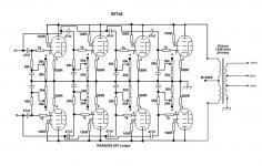
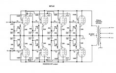
You are driving 8 triodes instead of the usual two pentodes. Triodes (and triode wired pentodes) have a larger input capacitance than a pentode. You have 4 in parallel on each side. The customary phase splitter as a driver design will not work here. You will need to add a cathode (or mosfet) follower between the phase splitter and the output stage.
I included the schematic of the power amp section of a 300 watt bass guitar amp. Note the two stage amplifier between the phase splitter and the output tubes. This amp uses 6X 6550's in pentode mode. You will be driving even more capacitance than this design.
Attachments
jane said:Shawn,
The 50k/47n RC will give you a roll off frequency at 68Hz, isn't that a bit high?
Jan E
Quite so, I thought for some reason they were 470nF - I'd recommend 220nF and I would probably change those 50K resistors to 100K which will help with the loading issue on the driver stage, and push the -3dB corner down to about 8Hz. Note this will not help with cmiller so a fairly robust driver stage is still required for good HF response.
kevinkr said:
Quite so, I thought for some reason they were 470nF - I'd recommend 220nF and I would probably......
I generally do not use nanofarad caps in my tube amps. Microfarad caps sound reliably better (because for this old fart the chance of putting in the wrong value is 1000% less).
So many Cathode followers
I'm making some more updates as per the suggestions but I got to ask; with so many types of cathode followers to implement, what would a typical selection be for the type of output circuit I am suggesting.
ie. totem pole, circlotron, White, Broskie, SRPP and grounded vs non grounded.
Thanks again for sharing your thoughts. My copy of Morgan Jones is in the mail. I hope I have it early next week. Got alot of reading to do.
Shawn.
I'm making some more updates as per the suggestions but I got to ask; with so many types of cathode followers to implement, what would a typical selection be for the type of output circuit I am suggesting.
ie. totem pole, circlotron, White, Broskie, SRPP and grounded vs non grounded.
Thanks again for sharing your thoughts. My copy of Morgan Jones is in the mail. I hope I have it early next week.
Got alot of reading to do. Shawn.
Source follower. You need current, it's got current. You need low source Z, it's got low source Z, and small enough to make using individual followers for each output tube be practical. That allows direct coupling to each tube's grid. When you get your copy of Jones, take a look at how he sets up the CF and output stage of the Crystal Palace amp.
If you want to do a tube CF, go for transconductance ueber alles. 6C45 or something manly-man like that. I'm goofy enough to consider trying a 6528.
If you want to do a tube CF, go for transconductance ueber alles. 6C45 or something manly-man like that. I'm goofy enough to consider trying a 6528.
Much has been written about the "sound" of TRIODE cathode followers and mitigating persceived problems it by current source loading them to put them in near constant current mode and bootstrapping them to put them in near constant voltage mode.
Valley and Wallman (have I got the names around the right way) suggest using Pentodes for cathode followers with the screens bootstrapped off the outputs and prove that on paper at least these perform better than triodes.
Kimmel suggested in his article on Mu Followers that MOSFET Source Follower was better again than a Pentode cathode Follower and so I have been using MOSFET Source Followers exclusively to drive output stages in my last 3 amps. I have not persceived any sonic problems with this. Just remember to maintain 25V or more Vds on the positive most voltage swings to keep device capacitance down - easy to do by selecting the right rail voltage for the drain.
One mans opinion and there are plenty who will disagree although I seem to sense that SY and I might be "on the same page" with this.
If you insist on a "Sandless" amp then White Cathode Follower is probably the way to go.
Cheers,
Ian
- Status
- This old topic is closed. If you want to reopen this topic, contact a moderator using the "Report Post" button.
- Home
- Amplifiers
- Tubes / Valves
- Eight 807's in Push Pull?