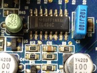
Have here an Eclipse XA5000 amplifier that is not powering up. When remote is applied, the logo lights up for a split second and then goes out. None of the heatsink mounted transistors are shorted or appear defective. To start, I measured the voltages on the TL494 IC since I am not getting any drive voltage to the PS FETS gates.
TL494 IC
Pin1 0.0
Pin2 1.4
Pin3 0.0
Pin4 4.8
Pin5 1.4
Pin6 3.5
Pin7 0.0
Pin813.3
Pin9 0.0
Pin10 0.0
Pin11 13.3
Pin12 13.3
Pin13 4.8
Pin14 4.8
Pin15 7.9
Pin16 4.8
I know some of you can identify issues just by looking at these readings
TL494 IC
Pin1 0.0
Pin2 1.4
Pin3 0.0
Pin4 4.8
Pin5 1.4
Pin6 3.5
Pin7 0.0
Pin813.3
Pin9 0.0
Pin10 0.0
Pin11 13.3
Pin12 13.3
Pin13 4.8
Pin14 4.8
Pin15 7.9
Pin16 4.8
I know some of you can identify issues just by looking at these readings
If anyone is going to do amp repairs, they should take an hour, a day, a week and do nothing but study the TLx94 until they know precisely how it works. A week may seem like a long time but if you do the work (even intermittently) for the next many years, you will virtually never have any question about the IC. You'll be able to look at the voltages and know precisely where to go next.
Pin 4 is causing the IC to stop producing output. It should be very near ground. Find what's driving that pin high. When you do, you can disconnect the driver to pin 4 and the amp may power up, showing the fault that's triggering the protection circuit.
Pin 4 is causing the IC to stop producing output. It should be very near ground. Find what's driving that pin high. When you do, you can disconnect the driver to pin 4 and the amp may power up, showing the fault that's triggering the protection circuit.
Thanks for the constructive advice regarding the TL494, will take it under advisement.
Regarding the 4.8v on pin 4 of this TL494, the pin is directly connected to C10 and R8 directly in front of the pin. On the other side of this capacitor and resistor, I get 0.0v with remote power applied. I could not find any other components that are directly connected to pin 4, but I haven't pulled the board out of the chassis.
Is it possible that the IC is defective? Or am I just not locating all components directly connected to pin 4?
Attachments
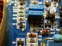
Found that pin 4 goes to a transistor or diode location Q4. If I lift the collector of Q4 the 4.8v on pin 4 is gone and the PS FETS receive drive voltage. I did not leave the amp powered up since I do not know what problem the amp has that lifting Q4 is bypassing. Q4 is an smd component with P8 written on it.
Can I proceed to test for audio with Q4 lifted?
There is a resistor location next to Q4 labeled R48 that is unpopulated. This resistor location is connected to the (base?) of Q4. Should this location have a resistor in it?
Can I proceed to test for audio with Q4 lifted?
There is a resistor location next to Q4 labeled R48 that is unpopulated. This resistor location is connected to the (base?) of Q4. Should this location have a resistor in it?
Attachments

So I have tested all 5 channels and they play clean audio on the test bench. I only needed to spray out and clean the switches and potentiometers in the preamp input section as they were scratchy. The -3.2v on the output terminals disappears as soon as a speaker is connected and there is no more than. 01v of DC on any output terminal.
How do I repair the protection circuit? There is still 4.8v on the collector of the transistor I lifted to remove the voltage from pin 4 of the TL494.
How do I repair the protection circuit? There is still 4.8v on the collector of the transistor I lifted to remove the voltage from pin 4 of the TL494.
So I understand that the 4.8v passing through Q4 is from the 5v output of pin 14 of the TL494, so what I need to do is track down the 2v that is present on the (base?) of Q4. I will probably proceed to trace this circuit but I am hoping someone can offer some guidance that may help me out. Thanks.
Sort of found what is triggering the protection. I traced the trigger to a diode D570 that is located near the toroidal and power supply area. If I lift one end of this diode, the amp does not go into protection with Q4 and all the other components installed. This diode is fed by a resistor R598 which has 53v on one end and 53.9v on the other end.
The resistor is fed by a transistor Q573 which has 53.2v at base, 53.8v AR collector, and 53.9v at emitter.
I don't know what I am looking at here, what it means, or what it should be. I do know that when the diode D570 is in the circuit, it sends 0.7v to the protection circuit connected to pin 4. When it is lifted, the amp behaves normally, with all other components installed.
Attachments
Try to get a service manual:
United States | Global Network | Corporate Profile | About FUJITSU TEN
| FUJITSU TEN
United States | Global Network | Corporate Profile | About FUJITSU TEN
| FUJITSU TEN
So, contacted Eclipse tech department and they sent me the owner's manual. They said they do not have schematics or service manuals for their products as they ceased production since 2009. They referred me to contact United Radio.
What assistance can I receive from the forum at this point?
I am currently working my way backwards through the protection trigger circuitry on the other side of the diode D570, to try to find what can and can't remain connected and the amp continue to function.
What assistance can I receive from the forum at this point?
I am currently working my way backwards through the protection trigger circuitry on the other side of the diode D570, to try to find what can and can't remain connected and the amp continue to function.
It's my amp so I want to sort it out. Digging around in the protection circuit on the other side of D570 but I really don't fully understand what it is I am supposed to be looking for, other than to keep D570 from producing a + voltage output. This circuitry is for the sub channel so there is +54v and - 54v on some of the transistors and resistors along with some lesser readings. I don't feel as if I am actually fixing anything, just breaking the circuit via various components.
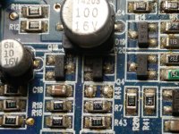
Is the output filter inductor supposed to be rather warm at idle with no input? Can only touch it for about 7-10 seconds before it is unbearable.
Is the output filter inductor supposed to be rather warm at idle with no input? Can only touch it for about 7-10 seconds before it is unbearable.
It's normal for some inductors to get too hot to touch. I don't know what's normal for this amp.
You have to find all of the components in the protection circuit. Then you have to determine which is defective or if some IC is sending a protect signal when it shouldn't be. This can be very time consuming.
You have to find all of the components in the protection circuit. Then you have to determine which is defective or if some IC is sending a protect signal when it shouldn't be. This can be very time consuming.
Very time consuming is correct. Sometimes a little bit of luck also helps. I spent the last few days just resoldering, probing, testing, removing and replacing components. Ended up replacing two resistors that got damaged during the process but they tested within tolerance before replacement. After reinstalling everything, the protection signal is gone and the amp plays clearly on all channels. Currently installed in a vehicle performing field testing but it appears to be repaired. Thanks again.
- Status
- This old topic is closed. If you want to reopen this topic, contact a moderator using the "Report Post" button.
- Home
- General Interest
- Car Audio
- Eclipse XA5000 not powering up