I am considering making the cabinet 12" deep instead of 14". That puts the 6" port 3" from the front and back wall. Will that be a problem? Inside dimensions are now 50x12x28.
My near final design is 220l tuned to 19.5HZ (target value, hehe, I just want to say I tuned into the teens). This will allow the port an overall length of 26", valve top to valve bottom. Using 2" Sched 40 PVC inside gives total port area that is 94.8% that of an 8", but more impressive, this configuration will have the equivalent diameter of (2) 8" ports! Go powerport!
Here is the last version of the spreadsheet attached.
Attachments
masterp2 said:Back to dual 6's in a powerport config, 28" each, this should work. Just have to flair, flair, flair.
I'm not sure that it will be so easy to tune 2 Polk Power Ports in the same enclosure, they would both have to be identical, and turning 2 identical Wave Guides (Valves) wont be easy either, well anyway very ambitious, I like it.
I am assuming that you approached tuning from adjusting the height of the wave guide, in your original plan. What was the volume?
No, actually I never tried to make mine operate acoustically like the Polk design, from what I understand the floor boundary is required to make the down firing Polk Power Port operate, mine needed to be up-firing so I just used the valve to close the port and it's somewhat decorative.
What is the diameter of the wave guide? Can you change the Fb by adjusting it? Is there an optimum Fb, i.e. a compromise between extension and SPL?
8.75" at the top, but effective area is only 8". As I mentioned above the valve is only good for open or closed operation, there seems to be no change in Fb with the valve in various positions, except for when it's almost closed you can hear severe wind rushing around the valve seat. Also I don’t like the sound of extremely low tuned enclosures, IMO 18Hz is as low as I would ever go anyway.
I'm not sure that it will be so easy to tune 2 Polk Power Ports in the same enclosure, they would both have to be identical, and turning 2 identical Wave Guides (Valves) wont be easy either
Since this is all a theory at this point, my expectations are tailored to the likes of the Kitty Hawk flight, I'll worry about the Sr-71 when I recognize a depth charge as something other than my driver bottoming out.
Expand on what you mean with floor boundary. All polk designs I have seen are ports firing down, into a plate that is a large square wave guide. None of the patent reading, nor the software guide discuss the floor as an element of the design. Besides the usual floor coupling (exciting a node) what would the floor have to offer?
masterp2 said:
Expand on what you mean with floor boundary. All polk designs I have seen are ports firing down, into a plate that is a large square wave guide. None of the patent reading, nor the software guide discuss the floor as an element of the design. Besides the usual floor coupling (exciting a node) what would the floor have to offer?
It's my understanding (Through a word of mouth source) that the floor boundary is a continuation of the Wave Guide like effect that the power port is supposed to achieve. I have not tried any of this my self so I truly don't know for sure. I do know that my valve on top will not yield a significant audible change except when it's completely closed.
After looking at your project again, it doesn't really comply with the powerport guidelines, well, it does, but because of the relatively narrow inside rod, the results you are experiencing are, in theory, dramatically reduced. If your "valve stem" were 3-4" in diameter (of course, you have to do new wave guide), you could shave 5" (guess) off the port or have the existing length tuned 1HZ (guess) lower. For port length calculation, how much did you shorten that port, i.e. before powerport vs length including the powerport mechanism?
Do you acknowledge that having it in there DOES tune your port lower? Have you tested and confirmed it? Any numbers? I would think that it does, but only nominally, being so narrow and only one end.
I guess what I am confused about is that you said you abandoned the powerport concept, leaving it there as an aesthetic, but that IS a powerport.
I need a little help deciding which alignment to shoot for. My choices are a 180l box tuned to 21 or a 240l box tuned to 18HZ. These choices result from allowable port length constraints, and represent my extremes, so something in between can be picked My goals are to produce an ENVIRONMENT for movies like U-571 and Jurassic, while still having ok quality for music.
This will be a non-corner loaded setup right behind the listening position (direct radiating) with the driver firing into the sofa.
Port Experts, help me out here. Realizing that it is beneficial to have laminar flow upon port exit, is it desirable to have turbulent flow INSIDE the port? Some have recommended somehow roughing the inside area of the port. Why? What minimizes port compression losses(not port noise)?
Yeah, I like that too, but the ports end up a little too long (the max box height for aesthetics is limiting port length). So I've got 19HZ at 220l, or 20 at 200. My design will never see the room corner, so perhaps the Fb output will not be too boomy.
I know this isn't the approach that is optimal for sound, but would one of these alignments yield discernably worse results than your suggestion, in your opinion?
With some stuffing, tuning may lower a bit.
I recall that ThomasW, with his AS-15, targeted this driver at 160-180l at 19HZ and it turned out tuned to be 18.5. Since it is a well respected Sub, I probably shouldn't stray too far, and he has stated clearly more than once that going below 18 is a bad idea. If my hunch is correct, and my box produces an extra 2-4 dB at Fb than other designs have yielded, then the location (not corner loaded) should be somewhat of a wash. Am I on track?
I feel confident that a target alignment can be approached within 1-2 HZ of tuning. Since it could go either way, maybe 19 or 20 would be a better target. Don't know if it would be good to end up with a 16HZ box as I really won't be able to "shorten" the ports, unless I build a knock down port assembly, another idea. Tune it then glue it after tuning the PVC lengths, possible using 1/2" plywood shims on the cabinet bottom.
 Kingdaddy, Thanks for your continued support. I plan to start cutting MDF tomorrow. Ordered some roo glue, for the pvc/wood joints. I'm itchin to get dusty, as is Thomas, my 3 1/2 year old assistant. I'm starting to have more faith in this concept and have verified one tried and true project with the spreadsheet.
If anyone else would like to jump in here, please do so. I'll start posting photo's this weekend when it get's interesting, powerport fabrication will be a new WW challenge.
I know this isn't the approach that is optimal for sound, but would one of these alignments yield discernably worse results than your suggestion, in your opinion?
With some stuffing, tuning may lower a bit.
I recall that ThomasW, with his AS-15, targeted this driver at 160-180l at 19HZ and it turned out tuned to be 18.5. Since it is a well respected Sub, I probably shouldn't stray too far, and he has stated clearly more than once that going below 18 is a bad idea. If my hunch is correct, and my box produces an extra 2-4 dB at Fb than other designs have yielded, then the location (not corner loaded) should be somewhat of a wash. Am I on track?
I feel confident that a target alignment can be approached within 1-2 HZ of tuning. Since it could go either way, maybe 19 or 20 would be a better target. Don't know if it would be good to end up with a 16HZ box as I really won't be able to "shorten" the ports, unless I build a knock down port assembly, another idea. Tune it then glue it after tuning the PVC lengths, possible using 1/2" plywood shims on the cabinet bottom.
Kingdaddy, Thanks for your continued support. I plan to start cutting MDF tomorrow. Ordered some roo glue, for the pvc/wood joints. I'm itchin to get dusty, as is Thomas, my 3 1/2 year old assistant. I'm starting to have more faith in this concept and have verified one tried and true project with the spreadsheet.If anyone else would like to jump in here, please do so. I'll start posting photo's this weekend when it get's interesting, powerport fabrication will be a new WW challenge.

Tuning
If you want to get the Tuning spot on, use the figure that your modeling program gave you, add a few inches then use test tones to dial it in. If you have a CD burned with Sine Wave Tones at 1Hz spacing from 15Hz to 30Hz (make one) with a different tone on each track (10 Sec) then you can just change tracks with your finger lightly on the cone and when you get to the Fb the speaker will be relatively still compared to just 1Hz above or below, Hopefully you will be lower than your target, then trim about 1” per Hz to get the Fb right on target.
Good Luck with your project, I hope to see some pictures when you finish.
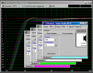
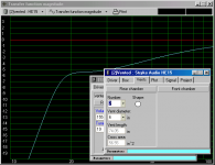
These curves were created with added mass, about 100g, maybe a good idea for creating this sub without EQ.
After looking at possible box volumes for this project, 160L is about the smallest (sofa) box I can fit an HE-15 and 2-6" powerports into. So I will be trying to duplicate the white curve with the hope that I will actually tune lower to eliminate the "ski jump" of the large EBS. Note, the pink curve is very close the ThomasW AS-15.
I have switched to using 3" shed 40 , 3.5" OD, for the wave guide connector, as this will tune to a more appropriate Fb (2 HZ lower than 2"). The tradeoff, the area is reduced. Total area will be 30% more than a single 6", instead of the originally targeted 50%. Effective diameter will still be great, equivalent of 2-7" ports, 70 in^2 total. Seems strange because the port exits are only 1.25" wide (9" circumference) with 3.5" PVC inside of 6".
But all of this (if the spreadsheet holds up) make for a very aesthetic small enclosure potential. If my wife likes it, it will be a double wammy.
Attachments
Final dimensions:
dim A dim B dim C (ht)
ID inches ID inches ID inches
40 12 26.5
Shooting for 155l, 5.5cf @ Fb=19
Please check my math, with 2-25" long, 6.625" OD powerports.
Each 25" port (overall 32" long including waveguides) houses the same acoustic mass as a 70" long port 6" in diameter. Exit area equivalent to 2 7" ports, port area 50% more than the AS-15.
CONVENTIONAL PORT EQUIVALENT
Diameter 6.00inches
Length 70.00inches
p - density of air 1.18kg/m^3
Sp=pi*(Dia/2)^2 - Cross-sectional area 28.27inches^2
MAP2=(p*1.46*Dia./2+p*Length)/Sp 122.21kg/m^4
This is the smallest practical box I can design with 2-port 19HZ tuning, and enhanced port area. I think the AS-15 was 180l.
Attachments
ThomasW, I hope I don't offend when trying to relate my project as an improvement to your own. I have modeled my own design trying to be unique, but I understand the AS-15 as the reference from which to compare others, though I've never heard what a truly nice DIY sub sounds like. So the AS-15 has been the platform for this project.
I just want to do something different without straying too far from success, that is why your sub comes up frequently. In my case I am going for an aesthetically small, with optimal performance sub with the cababilities of the AS-15.
I just want to do something different without straying too far from success, that is why your sub comes up frequently. In my case I am going for an aesthetically small, with optimal performance sub with the cababilities of the AS-15.
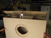
Settled on minimilistic optimization, 135l, inside dims are 40x11x26 tall.
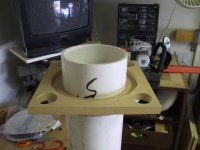
Photo shows the port frames at the top. Actually I still have to router the rabbet for the 5/16 PVC wall. The PVC will not be visible in the final product. A large roundover will be at the port exits.
Photo shows the port frames at the top. Actually I still have to router the rabbet for the 5/16 PVC wall. The PVC will not be visible in the final product. A large roundover will be at the port exits.
Attachments
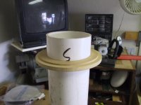
This was fun to make. It is the internal port support/cabinet brace. It is actually 2 pieces, a sleeve that will be bonded to the PVC and the square bracket that is part of the cabinet. The 2 pieces mate male/female with a rabbet, for centering purposes.
The inside end of the PVC will have a flair sleeve attached to it, the bracket in the photo has an oversized diameter so I can insert the flaired PVC through it at final assembly.
The inside end of the PVC will have a flair sleeve attached to it, the bracket in the photo has an oversized diameter so I can insert the flaired PVC through it at final assembly.
Attachments
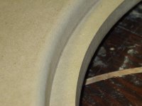
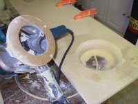
This is the top of the cabinet. Shows the first of 3 passes with the massive roundover bit, which weighs half a pound. Turned out to be no real problem handling it after I made a custom router base wide enough to utilize it. Variable speed routers only on this bit, turn it slower. I love the bosch. And the dust extraction is second to none.
Attachments
- Status
- This old topic is closed. If you want to reopen this topic, contact a moderator using the "Report Post" button.
- Home
- Loudspeakers
- Multi-Way
- EBS: Powerport application