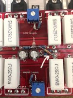
Do you know the reason for those caps? Is it to provide loading for the fb loop so that transients/ noise does not enter the signal path? If so it will try and short out those signals, but let DC pass and be fed back.... just thinking out loud, I don't have my amplifier handbooks unpacked yet, so not sure...
As they only carry a 63v rating, and are co-located with the rest of the bias circuit, I'm assuming that they offer some filtering or stabilizing effect for the current source, or are even in the (feedback)signal path.
I should have poked around to try and get an idea of what exactly they do, but didn't bother. I did look up the data sheet for the electrolytic parts and they basically look like a Panasonic FM maybe or close, so I thought they may be fine with a little help. Will be even better after a few days, as is the usual case with those fkp parts.
At this point it is icing on the cake, sounding very nice!
At the low cost that these boards are, maybe I should get a second one and draw out the circuit? The spare board could be tucked inside the amp case as a spare...
Wow, that is a great offer, the only problem is that I will be without any free time and likely the space to conduct my hobby here in a couple weeks or so. Am preparing for some semi-long term house guests and will be in the thick of it when the board would arrive...
I'm trying hard now to balance that effort while finishing up this amp so it can be sent out into the world.
I do wonder if some good pictures of each side of the board would produce any meaningful results?
I'm trying hard now to balance that effort while finishing up this amp so it can be sent out into the world.
I do wonder if some good pictures of each side of the board would produce any meaningful results?
Bridging the kit.
I was able to successfully bridge the kit quite easily. All u need is a 22k resistor and a 2" jumper cable...
Make one channel master and the other the slave.
1) Short the input of the slave as a start since it will get its signal from the master.
2) Solder the 22k, one side to the output line of the master, and the other end, to where the FB line goes back to the slave.
Basically the output of the master is providing FB to both channels, but in one case there is a normal input, and in case of the slave, there is zero input (see Step #1) and thus any FB provided with respect to zero input will result in an inverting signal on the slave. So of the 2 FB loops driven by the master, one runs inverted (slave) and the other runs non-inverted (the master) and the outputs of both channels are out of phase to each other and thus tie a load across the 2 hot sides and you have a bridged output.
Considerations:
1) Keep speaker leads short and not parallel to any AC mains wire since that line is used as FB for both channels and will thus be amplified twice and you might hear hum induced by stray wiring.
2) I would not run loads lower than 8 ohms bridged unless you have matched output devices... you can try, but its risky. With a robust supply, you can get Dynamic peaks of over 1000 watts, and similar numbers at clipping. For lower THD numbers, you might get 700-800 watts bridged.
3) I did see bias jump higher in a bridged scenario, requiring me to dial it down... this might be because he amp will run hotter while bridged (in my case it was a 4 ohm woofer which becomes a virtual 2 ohm load in a bridging scenario, that might have caused the amp to heat up twice as much, so keep an eye on heat and ergo, bias).
You can add a toggle switch to switch the amp from stereo to bridged, all u need is a dual gang type. When engaged, one gang shorts the input and the other connects the 22k from master to slave.
Good luck.
Attachments
Last edited:
Tough one to talk about... there are differences...
- I obviously got more power, I nearly blew my tweeter... luckily a thermal fuse dialed down the power to it. Basically you can make the amp to play louder, cleaner, making you forget for a moment that you will be crossing a few thresholds along the way... for woofer applications, its a no brainer, they need more power.
- I would not necessarily use this current set up to run mids/ tweets because ... too much power. The mids seemed to get a little a thin, ............. but more detailed.
- However, If you have a dark sounding speaker system, this will be a good thing... I felt imaging got a little deeper with more air around the instruments. The non-bridged version was a tad veiled in contrast, however it would have a little more bloom. I would think in a bridged set up, the components are more gain/ current starved leading to a more analytical sound. I might try and experiment with keeping the bridged scenario and lowering the rails and see if I can keep the sound softer and detailed at the same time... lets see... the wife's bugging me to get the home theatre up and running, so need to quit playing around.
-I ran it with only test speakers, which are a 3 way box with a 12" woofer, 5.25" vifa mid and generic tweeter in a 80's era Pioneer rack system box... at higher volumes, I was getting gusts of wind blowing my face about 4-5 feet away from the ports of the reflex...")
- I obviously got more power, I nearly blew my tweeter... luckily a thermal fuse dialed down the power to it. Basically you can make the amp to play louder, cleaner, making you forget for a moment that you will be crossing a few thresholds along the way... for woofer applications, its a no brainer, they need more power.
- I would not necessarily use this current set up to run mids/ tweets because ... too much power. The mids seemed to get a little a thin, ............. but more detailed.
- However, If you have a dark sounding speaker system, this will be a good thing... I felt imaging got a little deeper with more air around the instruments. The non-bridged version was a tad veiled in contrast, however it would have a little more bloom. I would think in a bridged set up, the components are more gain/ current starved leading to a more analytical sound. I might try and experiment with keeping the bridged scenario and lowering the rails and see if I can keep the sound softer and detailed at the same time... lets see... the wife's bugging me to get the home theatre up and running, so need to quit playing around.
-I ran it with only test speakers, which are a 3 way box with a 12" woofer, 5.25" vifa mid and generic tweeter in a 80's era Pioneer rack system box... at higher volumes, I was getting gusts of wind blowing my face about 4-5 feet away from the ports of the reflex...
Last edited:
I see that you are having a similar impression that I have noticed about how the tweeters tend to get hit hard; my magnepans are original from 1981, and this amp will make the tweeters buzz a bit if played loud. My other amp hasn't done that. Guess I need to service those panels...
I am wondering if there is a peak associated with the 47uf caps (low esr) that appear to be in the feedback loop, or at least attached to it. If I had the similar value parts in something like a muse bp, I would have tried them.
Great subwoofer amps I would think.
I am wondering if there is a peak associated with the 47uf caps (low esr) that appear to be in the feedback loop, or at least attached to it. If I had the similar value parts in something like a muse bp, I would have tried them.
Great subwoofer amps I would think.
The bass is indeed tight and punchy! It needs a minimum of 40,000uF per channel for the thunderous bass. I have 4 channels mounted on one large heatsink. its a 24lb monster. 3" x 8" x 15" half an inch thick walls. I have 2 of these sinks for a total of 8 channels. These will be bridged to 4 channels of 600-800 watts to drive four 15" woofers. 2 are Subs (Stryke Audio/ Acoustic Elegance types) and 2 are the jbl 2035hpls which play kick drums very well...
the second heatsink is mounted with 2 boards. It awaits power up and testing...
the second heatsink is mounted with 2 boards. It awaits power up and testing...
Ouch, that sucks!
I am feeling especially lucky now, and just hope that I can put the lid on it here quick before something like that happens.
Might be time for another board if you can't narrow it down very soon, fix that one for a spare maybe. It sounds like you are on the hook for the audio portion of the home theatre...
I think I found the issue... my bias trims were turned up all they way :-D . So when I powered it up, the amp kept tripping the inrush limiter I have, so it was power oscillating the inrush circuit causing the turn on squeal... rookie mistake
I did re-attache the ground, can't say for sure if that was the issue or if I had 2 issues... if I did, the trims saved the amp and alerted me :-D
I did re-attache the ground, can't say for sure if that was the issue or if I had 2 issues... if I did, the trims saved the amp and alerted me :-D
Great, I am glad you are liking the sound better now. I have heard the Dh500 and it sounded dull to me, so when you said you preferred the sound of it to this I was a little disappointed, I hope now they both seem good, if different.
About the Mial .01 poly, by bypass do you mean in parallel with the mkp or from it to gnd?
In the end I did find a grounding issue, missing trace on one side... the turn on bulb has saved me a lot of blown devices and time over the years...
I am wondering if I should buy a couple of spare boards for parts or replacement... the price has jumped 12% in 2 months... I have 4 boards running, perhaps a worthwhile investment...
I thought I had noticed the prices creeping upwards, wasn't sure though.
The polystyrene bypass I tried was parallel to the larger 10uf Mkp1848 input capacitors.
Glad to hear you found the issue, must be a huge relief.
My Hafler was indeed very dull when I had first listened to it, can see how it isn't very well received. After looking at the components that it had, I wasn't too surprised. After many replacement parts and some additional decoupling, things are very nice. Most of this can be found by looking at what Borbely had done later to much similar designs.
I have bypassed the main caps with 100v 100uF Elna Silmic II's and further bypassed with 103k films. I think its softened the sound some more.
Here is a pic of all 8 channels mounted on 2 huge heatsinks. All bridged, it will give me 4 channels of 600 watts RMS into 8 ohms. If I run 4 Toroids, I could get more.... but thats enough for me speakers...
I am waiting for speakon connectors to start hooking these up. The last piece is hooking all these up to two 15amp circuits and have them soft-started... looking at my options...
Attachments
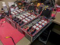
Wow, that's quite a display of power! I hope it gets along with the house circuit breakers!
If you can get the 100uf closer to the board, they may work better. You might consider a basic snubber on the rectifiers also, I used a .01uf across the transformer secondaries right on the rectifier, and then a .1uf in series with an 18 ohm R in parallel with the .01uf.
I'm actually pretty blown away that mine is sounding as good as it is...
This amp was in the last stages of completion when the bad thing happened. I fear that the cause may have been one of my polystyrene parts on the drivers, looked like a bad joint upon examination.
Two shorted outputs, and likely more, is going to have to sit for a while as I have other things going at the moment.
Two shorted outputs, and likely more, is going to have to sit for a while as I have other things going at the moment.
- Status
- This old topic is closed. If you want to reopen this topic, contact a moderator using the "Report Post" button.
- Home
- Amplifiers
- Solid State
- Ebay kit looks interesting. 300w @ 8 ohms dual channel