Added a picture of the dodgy soldering of the caps for doctormod, to check for possible cracking.
images upload
It would certainly be a first for me but I'm sure some must short out.
In the pic it looks more likely a short between the inductor leads, but they are bent away in the installed module!
An externally hosted image should be here but it was not working when we last tested it.
images upload
It would certainly be a first for me but I'm sure some must short out.
In the pic it looks more likely a short between the inductor leads, but they are bent away in the installed module!
Well, this could crack/break the MLCCs termination which can't easily be seen and is prone to a long-term defect. Think about what would happen if they short.
Ah-ha - mystery solved!!
The actual surface mount devices can crack and short due to both sides being anchored to the board - potentially generating huge stresses.
surface mount - Reliability and failure mode of MLCC (chip capacitors) - Electrical Engineering Stack Exchange
So my leaded Panasonics are perfectly safe, but all the ones that came soldered to the board are potentially dodgy.
So the big question is: will the speakers be OK if a short develops in any of the MLCC chip capacitors?
I did note that for about £4.30 I can buy a delay board and speaker protector all-in-one which looks quite useful. For burying a Sure 3116 in my (other) retro Sony shell that might be just the ticket - saves hunting for the mute pin
") .
.Digital Amplifier Speaker Protection Board BTL for TDA7492 TDA7498 TPA3116 | eBay
I haven't had much of a thump switching on my modded TDA7498 board - despite replacing the inadequate and nonlinear 470n input caps with 3.3uF PP caps. - not sure why that is. The 3.3V regulator seems to run close to the edge though - I think that's why the 20V input didn't work, that was only up to around 2.93V then. So maybe the board only wakes up around 21V and it's only got a 9V rise (to 32V) to deal with.
Guessing here though.
Hmm, i had a picture in mind where you soldered trough hole caps in parallel with their SMD parts. (Like on the input section) But after looking again, you removed the SMTs.
Crack problems may occur if the board is mechanical stressed or bended. This may also occur if it is fixed by its end points (screw mounts) and then heated alot.
They normally wont, but keep this in mind. More easy to crack those contacts is by soldering something in parallel with a long "lever" which then puts strain and vibration force to these termination caps.
For the 3.3V regulator, just think about what it has to dissipate.
20V - 3.3V = 16.7V. At 50mA load current, thats ~0.85W. You can spread the heat with a series resistor in front of the regulator, but you'll need to know the load current at the 3.3V first. Lets assume 50mA here.
At 20V, we share the drop to 6V at the regulator and 10.7V at a series resistor.
Rseries = 10.7V/0.05A = 214Ohms -> 220Ohms taken, 0.55W heat is dissipated here, so choose a 1W type. The regulator then only needs to dissipate 6V*0.05A = 0.3W.
You'll have to calculate this again for the worst case minimum input voltage to not drop to much on the series resistor then, because this may lead into dropout operation at the regulator.
I suspect it may be on too large a resistance, probably with an inadequate cap. Shame all the tracks and PCB are painted black - it makes it _very_ difficult to find what goes where - total DIY nightmare.
This board looks rather better to follow:
TDA7498 100W+100W HIFI Class D digital amplifier Board 12v 24v car AMP Audio | eBay
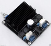
but this board looks better out of the box:
TDA7498 100W + High-power Digital Amplifier Board AMP Board with Radiator 100W | eBay
although if I'm pulling the filters off anyway the quality of those bits is irrelevant
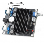
.Added a picture of the dodgy soldering of the caps for doctormod, to check for possible cracking.
An externally hosted image should be here but it was not working when we last tested it.
images upload
It would certainly be a first for me but I'm sure some must short out.
In the pic it looks more likely a short between the inductor leads, but they are bent away in the installed module!
i once tried to put bigger inductors in place.
that was because i got too heavy distortion when i tried to drive big subwoofers with this amp and i thought it be because of saturating inductors.
there was absolutely no effect, so i ended up putting the stock inductors back in place.
the amp sounds quite good in stock form within its range of application.
if the mods do not have anything to do with matching the output filters to specific speakers, i wouldn't touch it.
the only thing it really needs is a swap of the power cap.
i once had a cap exploding on one of these boards.
chemicon kzn do the job for me since that incident, but any other high quality cap should be fine, too.
did you guys recognize the sanwu TDA7498?
it looks quite promising to me.
the only thing i don't like is the huge heatsink, which causes long traces.
TDA7498 Klasse D 2X100 Watt Dual Channel Audio Stereo 80 Watt + 80 Watt Digitale Verstrkerplatine Modul freies Verschiffen in TDA7498 Klasse D 2x100 Watt Dual Channel Audio Stereo 80 Watt + 80 Watt digitale Verstrkerplatine Modul aus Verstrker auf
edit:
on a second look the heatsink might be smaller than on other boards.
it is only four times as long as one of those tiny caps.
...i ordered one...
Last edited:
having a sick note for the rest of the week allows me to go on a journey of discovery on aliexpress.
another new sanwu board spotted:
TDA7498E digital stereo verstrker brett 2X160 Watt BTL220W mono digitalverstrker power in High-Power Stereo-Klasse-D-Digitalverstrker Verstrker Chip: Original TDA7498E (tda7498l ist 2x80 watt Chip aus Verstrker auf AliExpress.com | Alibab
i wanted to try the TDA7498E for a long time.
it is not really low cost for the standards that sanwu set lately.
but it comes with features like gain setting options and mono btl jumpers.
the only dump thing is the pre mounted ventilator.
maybe there is a way to change it to a low noise - long life computer vent.
maybe it is not needed anyways....
And some another sanwu boards with different layout:
http://www.ebay.com/itm/TDA7498-2-1...597242?hash=item1a1098c5ba:g:c-QAAOSwBnVW9LF5
TDA7498 2 100W 2CHANNEL Digital Audio Amplifier Board High Power DC 8 32V A6P9 | eBay
Any advantages over the old ones?
http://www.ebay.com/itm/TDA7498-2-1...597242?hash=item1a1098c5ba:g:c-QAAOSwBnVW9LF5
TDA7498 2 100W 2CHANNEL Digital Audio Amplifier Board High Power DC 8 32V A6P9 | eBay
Any advantages over the old ones?
Last edited:
Hi guys, what do you think is the best TDA7498 board for ~20$ at the moment?
I need one for a single 8 Ohm PA Speaker(Mono). So do you think I get better Results with a mono PBTL Board(e.g better damping factor) or should I stick to a good stereo Board and drive one channel with a dummy load and no input? And how easily is it to mod a board to pbtl?
I need one for a single 8 Ohm PA Speaker(Mono). So do you think I get better Results with a mono PBTL Board(e.g better damping factor) or should I stick to a good stereo Board and drive one channel with a dummy load and no input? And how easily is it to mod a board to pbtl?
you should look at the tda8932 thread.
the mono btl board discussed over there should be taken into your consideration.
afaik three other boards are not tested so far, but look promising for your application.
TD7498MV (mono version of the chip):
Mono 100 Watt high power digitalverstrker bord HiFi mono verstrkerplatine TDA7498MV verstrkerplatine in Tda7498mv hoch- macht digitalverstrker bordtda7498mvist derzeit auf dem Markt erste100wvonBTL AusgangGewidmet verstrke aus Integrierte Schalt
TDA7498E (versatile variant of the chip with pbtl option onboard):
TDA7498E digital stereo verstrker brett 2X160 Watt BTL220W mono digitalverstrker power in High-Power Stereo-Klasse-D-Digitalverstrker Verstrker Chip: Original TDA7498E (tda7498l ist 2x80 watt Chip aus Verstrker auf AliExpress.com | Alibab
TDA7498 mono (STM says it doesn't work but here is a chinese product):
F98 2016 neueste Freies Verschiffen Assembled Klasse D Amp Bord TDA7498 Subwoofer Verstrkerplatine 150 Watt Modul Newfree verschiffen in Mit Original TDA7498 Importiert Elko 2200 uf/35 V Elektrolytische gewhrle aus Verst
I already considered the yuanjing TDA7498 blue mono boards, but they have a built in low pass filter.
Sorry, i overlooked that.
I have a similar problem:
For an outdoor speaker i want to use two 12" woofers (4Ohm, 93db-95db) and a big horntweeter (8Ohm, 100db-105db).
I currently consider to power it with two 12V slas via a TAS5611 for the woofers and look for mono board for the tweeter.
I'm looking forward to see if the TDA8932 will be powerful enough for that application.
The TDA7498MV looks like the obvious choice, but it costs more than a black yj and the new sanwu stereo boards.
So JimBeam's consideration to use only one channel of one of these might be worth a try...
Any thoughts anybody?
Attachments
Ok, I've tested the tda8932 and was pretty disappointed, I'm reaching the thermal limit pretty fast(even with a tiny heatsink).
So I will just buy the TDA7498 from sanwu and use only one channel.
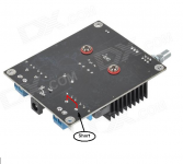
I have one last and pretty stupid Question:
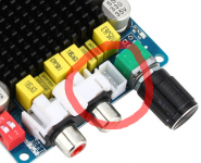
How are these connectors called?
So I will just buy the TDA7498 from sanwu and use only one channel.
I have one last and pretty stupid Question:
How are these connectors called?
Attachments
Yeah, and some boards use similar looking but smaller connectors.
My Sanwu TPA3116 board uses an 3-pin XH 2.54mm pitch connector (I hope, that's what I ordered). From the diagrams they provide, their TPA7498 uses the same connector. A different TPA3116 board I have (ChengZhi) has a similar but smaller pitch connector. Fortunately it came with a cable.
My Sanwu TPA3116 board uses an 3-pin XH 2.54mm pitch connector (I hope, that's what I ordered). From the diagrams they provide, their TPA7498 uses the same connector. A different TPA3116 board I have (ChengZhi) has a similar but smaller pitch connector. Fortunately it came with a cable.
Strange issue with on/off switches
Hello:
I'm running this board:
TDA7498 100W 100W Class D Amplifier Board | eBay
I've been having difficulty with power (on/off or SPST) switches failing or seeming to fail. Let me explain.
First, I mounted the amp on a board then put a board on the back side to fit binding posts, RCA jacks, and the DC power in jack. Yes, I know there is already a DC in jack on this amp board but I always remotely mount another on the back panel. Also, the on/off switch.
I'm using miniature (or sub-miniature?) SPST switches rated at 6 amps. I've tried three different types or manufacturers.
OK, so wiring goes as follows:
1) From the DC input jack on the back panel the + goes directly to what I've identified with my meter as + on the amp board (soldered a wire directly from the DC panel jack input to the underside of the amp board).
In other words, direct connection from back panel to underside of the amp board + to +.
2) With regard to the (-) connections. From the back panel DC input (-) lug to bottom of the switch, then top of switch to the (-) location on the underside of the amp board.
What is happening is this. Mostly, I just let the amp run. Sometimes, when I go to turn off the amp it will not turn off. The first time I thought the switch was just inferior and I soldered in another. The second time I experienced this I changed to a different brand of switch. Same thing, the amp doesn't want to turn off. Worked OK for a few days.
I tested the second switch for continuity and the switch seemed OK.
Today I had yet another switch do the same thing. Wouldn't turn the amp off. THIS, after operating fine for several weeks and I'd guess at least a dozen or more on/off cycles.
Any thoughts on what is going on?
Have I wired something incorrectly?
I think it's highly unlikely that 3 different brands of switches would do this. I could wrap my head around just getting a bad batch of junky switches, but not this.
Also, I don't understand why, when today I pulled the offending switch off, tested it, and it tested OK. So I put it back in and it's working now.
What I did today when I re-installed the same switch was put a cap across the switch leads. I didn't know if that would make any difference, but thought I'd try it.
Mark
Attachments
Last edited:
- Status
- Not open for further replies.
- Home
- Amplifiers
- Class D
- Ebay cheap TDA7498 boards