 incredible bottle, i thought the F2a11 was the biggest final pentode
Originally posted by coresta . What's an EL3010 ???
Hello ,
the TFK EL3010 ist the "Super E130L" and my personal candidate for a SPUD amp . The EL3010 is one of the latest german tubes , build only by TFK in Ulm , together with YL1260 and YL1350 ( also two very nice power tubes ) .
Regards , Alexander .
An externally hosted image should be here but it was not working when we last tested it.
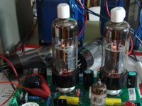
I have been digging into remote corners of my warehouse and finding some lost treasures. Last weekend's find was some WE 367A's and a box full of E130L's in several different brands. I modified a Simple SE board to test these tubes. The current setup uses 5K ohm OPT. I will try 3K transformers tomorrow. The Mullard (mand in England) tubes work the best distortion is 0.48 % at 1 watt. AT 8 watts the distortion is 2%. The Tungsram tubes have almost twice the distortion of the Mullards. The amp is wired in triode with no feedback. B+ is adjustable, but I have been using 350 volts. There have been no issues.
Attachments
 they don't like it ... and your 307A ?
 Hi George, don't go over 150v on screen
I have been warned! The data sheet that I have shows a maximum of 250 volts on the screen, and a maximum of 250 volts in triode mode. I dissected a broken tube and found the heaviest grid construction that I have seen, but they were closely spaced. Monster cathode too. I put these in a Simple SE in triode because that is what I have on my bench at this time. Long term plans are for a P-P amp with regulated screen voltage at a safe voltage level.
Last night I tried some National branded tubes that say "Made in Hungary", so I assume that they are Tungsram. I ran them at varying voltages up to 350 volts in triode. That puts about 325 volts across the tube. At about 350 volts the output breaks up into total distortion, but the tube current goes down. This appears to be a VHF oscillation. Both tubes exhibited this effect.
I also tried some Mullard branded tubes that say "Made in England" on them. The distortion numbers were about half of the National tubes. The breakup effect did not occur, but I did not go above 350 volts.
I also have some Mullard branded tubes that say "Made in Germany" and some Amperex tubes. I got these from someone who told me that he "removed them from power supplies". All tubes are used. Some are more used looking than others, one was broken. More experiments will follow, but I will be nice to these tubes because of their rarity. There will be no pictures of glowing tubes.... unless I find a bad one.
... and your 307A ?
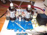
I bench tested the combination of Tubelab SE board, Hammond 272JX, and Edcor 5K OPT and found it to be excellent. I started construction on a complete amplifier several months ago using these components. I was working on it in an evening woodworking class that I was taking. The local school board abruptly cancelled the class due to "budget". No further progress has been made. I will finish it at some time, but I must do my wood working outside on weekends. This is unlikely in the Summer in south Florida. The daily temperature reaches 95F (35C) and it rains most every day.
I plan to try the 307A's in P-P mode soon as well. My 300Beast P-P amp needs to be rebuilt, or re made.
I also have some E130Ls(Mullard) that I am building a PP triodeamp from, with custom OPTs from Jack at Electra-Print.
Nice tube!
About oscillation it is recommended to solder a series 10ohm resistor in the topcap. Due to the extreme Gm of the tube it is as you say closely spaced.
Nice tube
!About oscillation it is recommended to solder a series 10ohm resistor in the topcap. Due to the extreme Gm of the tube it is as you say closely spaced.
150volts max average value  I use an 0A2 in screen to avoid runaway ... in a pass tube regulated PSU . 1kohm in G1 is mandatory too http://tubedata.itchurch.org/sheets/009/e/E130L.pdf
I use an 0A2 in screen to avoid runaway ... in a pass tube regulated PSU . 1kohm in G1 is mandatory too http://tubedata.itchurch.org/sheets/009/e/E130L.pdfsolder a series 10ohm resistor in the topcap .... 1kohm in G1 is mandatory too
I have a 1K grid stopper and a 150 ohm screen stopper on the Simple SE PC board. I will add the usual "ham radio" plate stopper which is about 10 turns of wire wound on a 100 ohm 1 watt carbon comp resistor (in parallel with the resistor). These were mandantory on 807 based RF amps in the old days.
That must be even better than the 10ohm.
It was standard practice on HF transmitters in the vacuum tube era. Often the tube would oscillate in the low VHF region (40 to 80 MHz) when you were attempting to make power at HF (2 to 30 MHz). The idea was to create a lossy VHF choke that would absorb power at VHF but pass the desired frequencies. I have used it successfully with sweep tubes, but won't know what happens here until I try it.
Every application is different due to the fact that an audio OPT presents an unusual load impedance at HF and VHF frequencies. If any resonances exist a transmitter will be born! It is not uncommon to see the results as interference on a neighboring TV set. I routinely scan my creations with an RF spectrum analyzer. Oscillations are not always visible with a scope, and the circuit may stop oscillating when probed. The 5842 is real bad about this.
I played music through the amp for 4 hours tonight. It does sound sweet. Tried 3K OPT at 250 volts B+ and 120 mA of current, and I tried the 5K OPT with 350 volts and 65 mA. The higher load / higher voltage sounded best to me. The numbers are hard to believe but they are correct. There is 36 volts across the 560 ohm cathode resistor, yielding about 65 mA of tube current. I loose 5 volts across the OPT so the plate voltage is 345 volts. The tube sees 309 volts and 65 mA which is a dissipation of about 20 watts. I am getting 8 watts out of this thing in triode mode at 2.5% distortion. That is 40% efficiency!
but your findings points towards something else........
I have always had a listening preference toward high voltage and higher than normal load impedance in SE amplifiers. This may be influenced by my speakers, and my preference toward large dynamic headroom. However the measurements do point to very good results at high load / voltage. Keep in mind that I was slightly over spec on the voltage. It worked great, but total operating time has been about 5 hours. The long term effects of operation at these voltage levels is unknown.
When you operate the tube at a higher voltage, more bias is required to control the current. This allows you to run more drive. If the tube likes it (remains linear) more power will result. In this case the plate will swing down to about 30 volts without distorting. Can't get there with a 6L6!
Careful measurements under various load, bias and supply voltage conditions has not been done yet. For now, I am trying to sort through a really large quantity of tubes to decide which ones to keep. I plan to crank through a dozen or more different potential output tubes this weekend. I will get back to these tubes later.
I bought a very large pair of Plitron P-P OPT's (400 watts, 1.2 K ohm) surplus last year. I have been looking for the right tubes to feed them. That section of the data sheet that shows 60 watts from a pair with a 1.6 K load keeps talking to me. 60 watts from a 300 volt supply with only 9 volts of drive, I'm thinking that a quad running from about 400 volts into 1.2K would just scream! Of course I could lower the supply, switch taps on the OPT, and run class A for about 30 watts too.
cool tubelab! tnx for the info.
Xactly my findings too, u can ran those tubes at higher voltages AND
the then possible (comparable) higher loadimpences are rewarding otherwise. Go to high and, among other things, k3, k5 aso will increase drastically. The trick is to find the "best results" at the highest possible voltage.
I think I'll use those tubes in a Ultra-linear arrangement with a g2-swing around 80-280-480V and a anodeswing of 80-480-880V
for a start.
Should give at least exceptional efficience ;o)
Just bougth a stach of zaerex branded E130L.
My idea is now to use em in a circlotron arangement, g2 fed from a adjustable, stabilized voltage source.That way the tubes run in a kind of ultralinear arrangement with the possibility to use a higher anodevoltage. The voltages will be arranged in a way so that Ua will high enough to never never swing below Ug2. Since it is 50% UL the g2 swing is only half of the anodeswing I would have in tride-connection.
I know beampower tubes would be better (tried 6146 with 400V Ug2 and 600V Ua with excellent results regarding power, efficience and distortion) but did not have a chance to try it with E130L yet, alltough 13E1 would be the total cracker,lol
If anyone know where to find good and cheap 13E1 please let me know.
Btw, this circlotron- 50%ultralinear-thingy (wich enables different voltages at g2 and anode) has huge advantages with low g2-voltage tubes.
To my knowledge, nobody else has published this idea earlier.
If you are a uncommerzial user, feel free to use it.
Otherwise, please contact me at:
messmer@kolumbus.fi
tubelab.com said:I have always had a listening preference toward high voltage and higher than normal load impedance in SE amplifiers.
On my bench near every tube showed a small increase in second coupled with very significant reductions of higher order distortions doing that. The preference here as well.
- Status
- This old topic is closed. If you want to reopen this topic, contact a moderator using the "Report Post" button.
- Home
- Amplifiers
- Tubes / Valves
- E130L in Triode mode