burnedfingers said:Look at the schematic
You will see the feedback taken off the 16 ohm tap on the secondary side of the transformer.
Burnedfingers, you know I never noticed that feedback loop off of the 16 ohm line before. It just never caught my eye - so much for paying attention to details. Now that I have had my PRK surgery, maybe I will notice more things like that.
Now, I understand (with the help of others too - credit given).
Changing the TAP
Burnedfingers, just for grins and giggles, I swapped the feedback loop over from the 16 to the 8 ohm tap just to see what the effect might be. It still sounds good. Weather it sounds better or not is (at least for me) too diffult to tell. It sounded good before, so I guess I could summarize by saying, "it couldn't hurt"...
I thought to myself that the 1K ohm resistor being in series with a 4, 8, 0r 16 ohm load is less than a 1% difference overall, so it couldn't hurt to try. I left the resistor and cap as is...I think it would be safer that way. After all, I'm trying to learn as I go - not create a smoke generator.
After that, I changed out the older "brownie" caps with the orange versions I purchased last week. Man, now THAT made a huge difference! [I actually thought about turning the bass control down a bit].
The bias pots are pretty much shot, so I ordered some new mil spec ones along with ceramic octal bases for the EL-34s.
For the moment, it's running in Triode mode nicely.
Brian
Re: Changing the TAP
The OPT secondary tap is the voltage source, 16R is 2x the output voltage of the 4R. The voltage divider is set between the 1k and 47R resistor in the input stage cathode.
cheers,
Douglas
brosenau said:
I thought to myself that the 1K ohm resistor being in series with a 4, 8, 0r 16 ohm load is less than a 1% difference overall, so it couldn't hurt to try. I left the resistor and cap as is...I think it would be safer that way. After all, I'm trying to learn as I go - not create a smoke generator.
Brian
The OPT secondary tap is the voltage source, 16R is 2x the output voltage of the 4R. The voltage divider is set between the 1k and 47R resistor in the input stage cathode.
cheers,
Douglas
Re: Re: Changing the TAP
Keeping in mind that I'm relatively new here, I see what you are talking about on the schematic, but how does your information apply in practical terms...or laymen's terms? How would changing the feedback line from one terminal to another change the output sound? All things being equal, and without changing any other devices, what affect would it have?
Wouldn't it make more sense to use the tap that the speakers are connected to anyway?
I've had a pretty steep learning curve over the past few weeks, and it's been a lot of fun, but I didn't expect a beating...

I love my amp and my new hobby as a result. In all of my years, I've been swamped with "black-box maintenance" and never had the opportunity to get this deep into the weeds until now. I just wished I'd done it 20 years ago. These tubes are just SO much more fun!
Brian
Bandersnatch said:
The OPT secondary tap is the voltage source, 16R is 2x the output voltage of the 4R. The voltage divider is set between the 1k and 47R resistor in the input stage cathode.
cheers,
Douglas
Keeping in mind that I'm relatively new here, I see what you are talking about on the schematic, but how does your information apply in practical terms...or laymen's terms? How would changing the feedback line from one terminal to another change the output sound? All things being equal, and without changing any other devices, what affect would it have?
Wouldn't it make more sense to use the tap that the speakers are connected to anyway?
I've had a pretty steep learning curve over the past few weeks, and it's been a lot of fun, but I didn't expect a beating...
I love my amp and my new hobby as a result. In all of my years, I've been swamped with "black-box maintenance" and never had the opportunity to get this deep into the weeds until now. I just wished I'd done it 20 years ago. These tubes are just SO much more fun!
Brian
K&K St-70 Mod?
Has anyone here tried the k&k mod for the Dynaco St-70? It's essentially a whole new driver board and pws. It uses an input transformer/phase splitter and runs the output stage in class A1. I am particularly interested in the sonic advantage of the amorphous core transformer over the mu metal version.
http://www.kandkaudio.com/poweramplifier.html
TIA for any comments.
Bob
K&K St-70 mod
A schematic would be helpful. I suspect that it's similar to the schematics for their PP inut stage and the PP Power amplifier. Both feature the input transformer /phase splitter.
The prices are a little more than some St-70 driver board replacements. The 'basic' kit is $285, pretty close to the Mapletree ($250) and the Welborne Labs ($295).
The K&K includes not only new driver circuitry, but a new power supply. Without a schematic showing voltages I'm not sure how they run the output tubes. I would hope that the voltages would be optimal for class A1 operation.
Just trying to get more information and especially first hand impressions.
Bob
ST-70 Renewed - SWEET!
Yesterday, I received a new bare board from Tubedreams to replace my original PC-3. The old one was in very bad shape and it was very unstable. Two days earlier, I received a package with some ceramic octals and two new bias pot (the military ones).
So, last night I completely stripped my ST-70 and rebuilt it. Now, it's rock-solid and working beautifully. These things are so incredibly simple, I don't know why anyone would want anything else...
BTW - I found a company on the net that offers FREE SAMPLES of chassis and project boxes for the DIY-minded. They advertise a wide range of items and offer any item less than $75 as a sample. I asked them to send me one to start my tube preamp project. When I receive it, I'll let you all know about it and them. In the mean time - happy listenning!
Brian
hey-Hey!!!,
The choice of amplifier/phase splitter stage is opened up if you've got a linestage with a bit of gain. Say a 5687 grounded cathode or 6SN7 with similar topology. An 'El Cheapo' design with another medium-mu triode is then an option. 5687, 6H30, 6H6Pi...or maybe if something like a 12B4 linestage is used try a pair of 6S4Pi-EV LTP. There's lots of options with the 6S4/6S45 type, and they have got lots of gain and plate Z well below 4k at moderate idle currents.
cheers,
Douglas
Originally posted by: brosenau
Burnedfingers, just for grins and giggles, I swapped the feedback loop over from the 16 to the 8 ohm tap just to see what the effect might be. It still sounds good. Weather it sounds better or not is (at least for me) too diffult to tell. It sounded good before, so I guess I could summarize by saying, "it couldn't hurt"...
I thought to myself that the 1K ohm resistor being in series with a 4, 8, 0r 16 ohm load is less than a 1% difference overall, so it couldn't hurt to try. I left the resistor and cap as is...I think it would be safer that way. After all, I'm trying to learn as I go - not create a smoke generator.
Hi brosenau
When you changed the feedback connection from the 16 ohm tap to the 8 ohm tap without changing the value of the fb resistor (1k) you lowered the amount of fb by about 3dB (I hope that's correct, need more coffee.) and that's why you heard a difference in the sound.
So if you have 1V @ the 16 ohm tap...
16 ohm = 1V = 0 dB
8 ohm = 0.707V = -3 dB
4 ohm = 0.5V = -6 dB
I hope that's right and if I'm wrong someone will chime in and correct me I'm sure!
And of course the output transformer is in the feedback loop and when you change what tap you take the fb voltage from and even if you adjust the fb resistor for the same amount of fb and depending where the speaker is attached there will be a difference due to all kinds of factors. Inductance, back EMF from the speaker itself, parasitic capacitance and so forth. Damping factor will change as well as the stability and fequency response or bandwidth if you will, of the amplifier. Speakers themselves will change what gets fed back (it's impedance is frequency dependent and all over the place!) and that's why you would use a non-inductive resistor for testing purposes.
I've had a pretty steep learning curve over the past few weeks, and it's been a lot of fun, but I didn't expect a beating...
Awww I don't think you getting a beating here.

We're all still learning here or we wouldn't be here!
Cheers
Wayne
edit: spelling
OK Wayne - I thank you too for that super lesson in FB loops.
In your opinion, would it be best just to leave the FB line secured to the 16ohm tap then? I'm not running in UL mode at the moment...I still have a couple of things I'd like to try before I connect the 70 to my Klipsch KM-6 speakers. For now, I'm still tinkering with it on the bench...connected to some bookshelf KLH sets through a passive sub.
I'm glad you all take the time to explain things - I can't seem to find many books on the subject in my local libraries. I
I did manage to get a subscription to AudioXpress - that's been a nice resource.
Brian
Solen FAST caps -
I was eyeballing a new PC-3 board on E-bay over the past couple days. The owner pushes a lot of hoopla about the Solen FAST caps he used to replace the old coupling capacitors. He likes them so much, he states they are better in sonic transparity than the touted orange drops.
Any opinions on these Solen caps?
- B
Quote:
A schematic would be helpful. I suspect that it's similar to the schematics for their PP inut stage and the PP Power amplifier. Both feature the input transformer /phase splitter.
The prices are a little more than some St-70 driver board replacements. The 'basic' kit is $285, pretty close to the Mapletree ($250) and the Welborne Labs ($295).
The K&K includes not only new driver circuitry, but a new power supply. Without a schematic showing voltages I'm not sure how they run the output tubes. I would hope that the voltages would be optimal for class A1 operation.
Just trying to get more information and especially first hand impressions.
Bob
Bob,
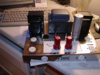
One can always build their own driver board. This is the third one I have built. Everything on this amplifier is left overs or scrap pieces. I have named it "Spare Parts 70". The HP transformer dwarfs the original in its ability to take care of the extra filament needs and runs super cool. What I have saved in making my driver board will take care of the cost of a power supply board or power supply mods.
A schematic would be helpful. I suspect that it's similar to the schematics for their PP inut stage and the PP Power amplifier. Both feature the input transformer /phase splitter.
The prices are a little more than some St-70 driver board replacements. The 'basic' kit is $285, pretty close to the Mapletree ($250) and the Welborne Labs ($295).
The K&K includes not only new driver circuitry, but a new power supply. Without a schematic showing voltages I'm not sure how they run the output tubes. I would hope that the voltages would be optimal for class A1 operation.
Just trying to get more information and especially first hand impressions.
Bob
Bob,
One can always build their own driver board. This is the third one I have built. Everything on this amplifier is left overs or scrap pieces. I have named it "Spare Parts 70". The HP transformer dwarfs the original in its ability to take care of the extra filament needs and runs super cool. What I have saved in making my driver board will take care of the cost of a power supply board or power supply mods.
Attachments
"One can always build their own driver board."
burnedfingers
It's great that you have the knowledge and experience to design and build your own voltage amp and driver circuitry. That's a little beyond me, and, I suspect, most folks here. While I could design and build something that would be stable and 'work', I do not have the time, experience and skill needed to design a really good amplifier. Fortunately there are people who have that knowledge and experience and are willing to share the fruits of their work. That includes the people who share their expertise on this and other forums (like yourself), and those who make St-70 driver board kits. For those with the knowledge and experience needed to build electronics (but not design them), the St-70 driver kits represent good value. Judging by the content in this thread and others, there is considerable interest in these kits. I doubt that any of these kit vendors is getting rich off the sales of these kits.
The K&K kit is relatively new, and takes a rather different approach. The cost seems fair even just considering the parts cost. I am curious about how it sounds, and how it compares with the other St-70 kits. I'm sure that none of them is perfect and that each has a unique set of strengths and weaknesses. It's really not about which kit is absolutely the best, but about personal preferences for the sonic strengths and compromises of each kit.
By the way, I too am curious about your St-70 board. Could you tell us a little more about it?
Regards,
Bob
By the way, I too am curious about your St-70 board. Could you tell us a little more about it?
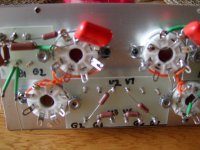
My Stereo 70 board is a tweeked Mapletree board. I have what I would like to think as better operating points plus I added a CCS to the long tail 6SL7. I generally use a 6Su7 in place of the 6Sl7.
The different resistor values plus the CCS make it sound superior to the Mapletree board in my opinion based on a side by side evaluation.
The schematic is online at Lloyds site. The values are not correct on his schematic however.
The board is not difficult to make at all. I made my own turret boards. There are three of them. The plate is a piece of scrap aluminum left over from a plate off a door.
Before anyone here gets excited about me making a similar circuit to what Lloyd sells the input portion of the circuit as well as the long tail can be found in several publications.
Picture of the board partially put together.
Attachments
ST-70 Transient Noise Spikes
I connected my ST-70 into my theater, thus replacing my Adcom SS power amp. I was absolutely delighted to the tone it produced through my Klipsch KM-6 speakers.
I discovered a weakness though that I'd like to remedy. When I walked across the room to turn off the lights in my acquarium, a noticable "POP" sound came through the speakers.
I suspected that the transient noise from the power circuit went unfiltered through the Dyna Power Supply. Would installing a capacitor across the primary side of the power tranny help to reduce this anomaly? If so, what value would you recommend?
- Brian
Re: ST-70 Transient Noise Spikes
I doubt that the aquarium lights pull enough current to disturb the AC mains. The most likely culprit is RF interferance that's getting into the front end via the gNFB connection and/or the input. You might need cables that have better shielding. RF is getting to be a bit of a problem these days since the useage of these new screw-in flourescent light bulbs that the likes of Algore are forcing down our throats. Those things are noisey in the longwave bands.
You can connect a capacitor across the secondary of the power xfmr. I use 0.01uF / 3KV units for transient suppression, and to protect solid state diodes from inductive kick backs from ripple chokes on power down.
brosenau said:I discovered a weakness though that I'd like to remedy. When I walked across the room to turn off the lights in my acquarium, a noticable "POP" sound came through the speakers.
I suspected that the transient noise from the power circuit went unfiltered through the Dyna Power Supply. Would installing a capacitor across the primary side of the power tranny help to reduce this anomaly? If so, what value would you recommend?
I doubt that the aquarium lights pull enough current to disturb the AC mains. The most likely culprit is RF interferance that's getting into the front end via the gNFB connection and/or the input. You might need cables that have better shielding. RF is getting to be a bit of a problem these days since the useage of these new screw-in flourescent light bulbs that the likes of Algore are forcing down our throats. Those things are noisey in the longwave bands.
You can connect a capacitor across the secondary of the power xfmr. I use 0.01uF / 3KV units for transient suppression, and to protect solid state diodes from inductive kick backs from ripple chokes on power down.
- Status
- This old topic is closed. If you want to reopen this topic, contact a moderator using the "Report Post" button.
- Home
- Amplifiers
- Tubes / Valves
- Dynaco Stereo 70 amplifier