I also found it rather funny to save to the extent of using a common cathode (bias) resistor for all four EL84s.
While this trick does save the cost of one power resistor and one cap section, I think there’s another, slightly more noble, reason that Dyna and a few other manufacturers used a shared cathode bias resistor among the four tubes in both channels. As the tube characteristics drift with temperature and aging (or if poorly matched tubes are used in a replacement), the cathode bias voltage is held at the average value for the four tubes. Any one tube going somewhat errant won’t change the average Vgk very much. Channel separation is maintained to the extent that the bypass cap provides a good AC short to ground. At very low frequencies where channel separation is generally acknowledged to be less critical, there would be some channel-to-channel crosstalk, but these effects are suppressed because the crosstalk is in the common-mode both to and from each push-pull pair. From the perspective of a trouble-free design for lowest common-denominator users, this approach made some sense.
However, we avid DIYers can and probably should separate the bias resistor and bypass cap, one each for each channel, if we don’t incorporate some more sophisticated biasing arrangement (fixed bias, LEDs, servos, or whatever).
the ST-35 runs the 6BQ5 way beyond its ratings...IIRC the screen and plate dissipation in the ST-35 probably exceeds 14W per tube.
This problem is a bit more vexing, especially with today's higher average AC line voltages. Besides taking steps to drop power tube voltages and/or currents, thermal support is useful.
I have an SCA-35 which has been undergoing a gradual transformation. In the SCA-35, the four 6BQ5s are arranged close together in a diamond arrangement. They are too close to each other for comfort and the heat build-up is alarming. The adjacent power transformer doesn’t help this situation. Often the PCBs in the SCA-35 are charred looking from all the excess heat over decades of time. Despite the perforated top cover, air circulation is not enough to keep inner chassis temperatures reasonable, in my view. I found a tiny box fan, just over an inch on each side, which I mounted on the inside of the perforated top cover so that the fan fits just within the diamond pattern of the four tubes with the cover in place. It is close to, but not touching any of the tubes. The fan accelerates air out of the top making the diamond shape into a bit of a chimney. The fan alone is not enough to protect a severely over-stressed tube, but it helps, and it keeps other components inside the chassis cooler. The ST-35 should run cooler than the SCA-35 due to its more spread-out arrangement, but a pair of small, quiet fans on the ST-35’s output tubes might be helpful too.
The single cathode resistor makes it more sensitive to tube imbalance - a tube with grid emission will run away for sure with such a low value. But matched quads of 6BQ5s were cheap then... I think it was done to squeeze the last fraction of a watt out of the 6BQ5s, albeit one channel at a time - it won't help with both channels driven.
Tom,
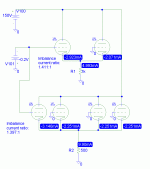
You are right about one tube in runaway. The lower-value shared resistor provides less negative feedback at "DC" to that one tube if it goes wild, which I have seen in my own SCA-35 with a glowing Ei EL84 (actually a relabeled 6P14). But, push-pull balance is still slightly better, as you can see in the sim result below. I used a small grid bias to unbalance one tube in each of the two cases (two tubes versus four tubes). By the way, total power supply current stays more constant with a shared resistor too. Admittedly, the improvement in push-pull balance is less than I recalled (in this quicky sim of 6DJ8s anyway), but it's definitely in the favorable direction.
I don't see how the shared approach could squeeze any more power out of the amplifier in the audio band where the bypass cap is an AC short.
Attachments
kevinkr said:I have never figured out why people ran EL84/6BQ5 so far beyond their ratings, but apparently Mullard, Amperex, Toshiba, and some US brands can survive long periods of operation at 100V and 25% - 30% beyond their dissipation rating. Current production can't quite.
I have some NOS RCA that definitely cannot be run this way as well so it is no reflection on the quality of current JJ production.
[/B]
Does the ST-35 really run the outputs so far beyond their ratings? From the RCA Tube Manual u/ 7189: A pair, runnning Ultra Linear, with a plate voltage of 375 and a 220 ohm cathode resistor (I'm assuming per pair!), has a zero signal plate current of 70 ma (again, this has to be for a pair), or 35 ma per tube. 375 X .035 = 13 watts, which is just over the rated 12, but not too bad. The Dynaco runs the plates at something like 350 volts (subtracting the cathode voltage from the total plate voltage), and a cathode resistance of 190 ohms per pair.
I do find it interesting that the the 7189 has a 400 volt max. plate voltage, while the 6BQ5's plate is only rated for 300, while the max. plate dissipation remains the same at 12 watts. Now I know nearly nothing about design of electron tubes, but it would seem to me that the only way that plate voltage ratings could be increased would be to increase the distance from the plate to the cathode, and grid. If this was the case, I'd think that the interelectrode capacitances would change, but the two tubes have exactly the same values!
I wonder if it doesn't boil down to--exactly what were the differances (if any) between a 7189 and a 6BQ5 in, say, 1970?
I believe David Hafler knew when he released this amplfier to the public specifying "6BQ5/EL84/7189 tubes", and the amplifier turned out to be be very reliable, as were nearly all of his designs.
Perhaps the 21st century marketing gurus were "cutting their teeth" on tube ratings 35 years ago!

ArtG,
W-e-e-e-ll, fine, the overloading is not that serious (remember that you are looking at total dissipation, including G2 so it is really 14W max.) In my case the h.t. was 385V and the total I=42 mA, i.e. 15,5W, but as someone said one is supposed to include room for mains variations.
Regarding max. voltages, I wish someone knew! According to a friend who worked at Philips Eindhoven in the 50s (assembling tubes), it is a kind of "operational indication". The EL84 Mullard data sheets of Feb. 1961 already gave Va(b)max. as 550V. Also you would have noticed that when used as a sweep tube the max. can suddenly become 4-5 times higher.
It does not have to do with electrode dimensions as you correctly conclude. Arcing as such will most likely occur across the spacers, thus you will notice that in later higher rated tubes (e.g. 6L6GC, EL34), there is a half-moon slit in the spacers, between the anode and other (usually g2) pins. Also, one gets shivers when one looks at some of the lead/pin separation distances down below (sharp points to boot), but it never sparks there. The 7027 has a Va max of 600V, the 6L6GC of 500V, with no difference in construction. There is also certain to be a safety factor, more so I would believe than with dissipation. (And just to be complete, the latter is of course at a certain ambient temperature! Our friends in Canada will have the advantage there.)
Regards
st-35
Just a quick note to let you all know that I am still following along. I have downloaded the Red Light District article from DIYMAG and periodically even stare at a printed copy of my ST-35 schematic. Its a good thin Thanksgiving is coming so II can catch up on my reading. The conversation here often takes a long looping arc over the depth of my tube knowledge.
Steve Swartz
st-35 heat problem/question
Sorry to resurect this thread after such a long time in the graveyard. I have finally rebuilt my st-35 more or less back a stock form with the aid of some nice boards filtercaps and a power tranny from dynacokitparts. Now that the thing works (I think) I noticed it runs really really hot. First I checked my line voltage and sure enough it was 124 VAC. So the first thing I tried was to put it on a variac and throttle the input voltage down to 117, then I took the protective cover off it to let it breath better and stuck it up on blocks so that more air could get underneath.
All this helped a bit and now iit takes maybe 35 minutes for the power transformer to really get cooking. So here is my question, is this normal for this amp? Is there a temperature which I can measure and make a go/no-go decision. How about a total current or power? If all else fails is there a way lower the heat build up in the power transformer. I admit my solid state finger-tips are not calibrated to the way tube amps a supposed to run so all this may be normal, I just hate to burn up another power transformer.
Thank Steve
If you are concerned use a small slow speed fan on top of the cage, works wonders.
The ST-35 normally runs very warm. High line voltage will walk the power transformer core up the BH curve towards saturation, and that will result in a lot of additional heat.
Long term solution to excessive line voltage (if that 124V was not a fluke) would be to take a >3A 6.3V filament transformer and wire it so that it bucks the line voltage down to a more reasonable 118V or so. Mount it in a box with a duplex outlet and you will be all set. Include a slow blow fuse rated at about the secondary current of the transformer for safety.
edit: for clarity
I'm currently building an external 6.3 volt DC filament supply which will provide power to both of my ST-35s (biamp) and eventually my preamp and active crosssover. The reason that I'm supplying the ST-35 heaters in this way is not that I feel that there's much advantage to running DC on the Dynaco amp's heaters, rather to reduce the total load on the power transformer. It's my hope that this will both result in a cooler transformer, and (at least in theory) better PS regulation.
I've been running a cooling fan on my amps for years, and strongly recommend it.
How do you like the sound, so far?
I've been running a cooling fan on my amps for years, and strongly recommend it.
How do you like the sound, so far?
Kevinkr,
Now why have I not thought of this before We have the problem with 230V sometimes being 246V. I have lots of low voltage trannies around. Thanks.
Sds 2000,
Amplifier power transformers should normally not get hotter than 60 degrees, i.e. what you can touch. (Also, excluding heat radiated there from close-standing output tubes - why do folks sometimes fail to attend to that?) Not so much that the transformer might fail, but it heats up the chassis and components to an unacceptable level.
In addition to above advice from other members, have you made sure the transformer is OK? (Perhaps old hat to you; one runs it for an hour with the tubes removed. It should not get hotter than low luke-warm.) I have also sometimes found that even with "normal" mains voltage, heaters would go to 6,8V. That is an indication that somewhere calculations went awry. I like to have heaters not higher than 6,4V under normal conditions, whatever the transformer says.
Regards.
Now why have I not thought of this before
We have the problem with 230V sometimes being 246V. I have lots of low voltage trannies around. Thanks.Sds 2000,
Amplifier power transformers should normally not get hotter than 60 degrees, i.e. what you can touch. (Also, excluding heat radiated there from close-standing output tubes - why do folks sometimes fail to attend to that?) Not so much that the transformer might fail, but it heats up the chassis and components to an unacceptable level.
In addition to above advice from other members, have you made sure the transformer is OK? (Perhaps old hat to you; one runs it for an hour with the tubes removed. It should not get hotter than low luke-warm.) I have also sometimes found that even with "normal" mains voltage, heaters would go to 6,8V. That is an indication that somewhere calculations went awry. I like to have heaters not higher than 6,4V under normal conditions, whatever the transformer says.
Regards.
Thanx to all
Thanks to all who have put in their nickels worth trying to help me. I'm pretty sure the power transformer is not to blame since the smoke and bubbly sound from the original convinced me it was time to change that unit out for a new one. With a variac I borrowed set to give me 117 VAC in and the chassis cover taken off the unit it does seem to pass the 10 second finger test. I guess at the very least a low noise fan and a 6.3 volt transformer used as indicated must be in order.
I have to say, the idea of an external filament source sounds very appealing since this will surely cut down on the heat dissipated
in the power trans allot. On the other hand it does seem like using 2 extra filament transformers to run a st-35 violates the "beauty-of-simplicity" spirit of the thing.
How does it sound? Well, at the same power lever its no match for my Transcended OTL T-16, but even with a completely new set of JJ tubes I doubt it came to 1/4 the price (and it has less then 1/3 as many tubes!). I'm holding off on final judgment till it runs a little more. Usually I don't notice allot of change during burn-in but this little thing has been slowly getting better and better. Maybe I should mention I don't have a pair of nice super efficient speakers and most testing has been done with my old stax electrostatic headphones so I cant say anything about imaging. The Stax box may be weird load too, I don’t know
Steve
- Status
- This old topic is closed. If you want to reopen this topic, contact a moderator using the "Report Post" button.
- Home
- Amplifiers
- Tubes / Valves
- Dynaco ST35