As you may know, I sell update kits for the Stereo 120. However, some folks like to keep their Stereo 120's stock. Here's a new page on the website with a collection of information about the original design. It might help those who want to repair theirs and keep it original.
Dynaco Stereo 120 Repair
Dynaco Stereo 120 Repair
Okay, I've built one of these circuits, and the idle voltage across the emitter/collector resistor R27 is 190 mv as pwg tang reported. This is too much for thermal stability IMHO. when the sense transistor of the djoffe closed loop feedback circuit blew for the second time, the ST120 ran for months with 220 mv of idle voltage (440 ma) which the fans I had installed on it protected the transistors.
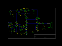
So I tried modifying pwg tang circuit for less idle current, see the schematic i drew.
Per the Apex AX6, I changed R28 the emitter resistor on the pnp driver from 3.3 ohms to 33 ohms (AX6 used 27 which I don't have). Idle current voltage was 256 mv minimum.
Per AX6 I added R31 a .51 ohm emitter resistor to the lower output transistor. Idle voltage minimum was 238.
Per AX6 I changed R7 in the power supply from 1.5k to 3.3k. Idle current voltage went to zero, because Q6 was turned off with 0.5 v on the base.
Per AX6 I changed the R14 the emitter resistor on the pnp driver from 100 to 220 ohm. Idle current voltage was adjustable from 46 to 64 mv, but the 1/4 watt resistor got hot and scorched the NEMA CE laminate board. I had to change it to 2 W.
Per AX6 I changed the R13 the emitter resistor on the upper driver to for symmetry to 220 ohm. Idle bias current voltage went to 55 mv non adjustable. the C12 output line, the "middle" of the single voltage scheme, went to 69 of 70 V. The device plays music that way, but I'm not connecting it to my good speakers to evaluate how good that is with that much assymetry.
The cause is that The base of Q2 is at 2.5 VDC and the emitter is at 3.6 v. So Q2 is not turned on except during the music cycle. I can't image cutting the bottoms off the input waveforms is good for fidelity.
I tried installing a .5 w 2.4 v zener diode across R8 the 270 ohm emitter resistor on Q2, and the voltage across R8 remained 3.6 v and the voltage at the base of Q2 remained 2.5. So Q1 has a collector voltage lower than the base voltage. Music passes through it but it is deeply saturated. changing the base resistor on Q1, R5, from 100k to 200 k doesn't eliminate the saturation. So Q1 has way too much gain, or I have another wiring error (I've found a few, I can't find this one).
I can't complete the AX6 schematic as i don't have PNP 80 Vceo transistors except for TIP32c, so Im going off in the direction of the National Panasonic SU380 quasi complementary amp ygg-it posted about the Bauxall diode, hoping it will work with no center tap on the transformer, and 72 v rail voltage instead of 44. Next to change is install a 400 ohm base resistor between Q2 and Q4. The current that blew the 2.4 v zener diode regulator I tried can't be coming through R9 the 4.7k from the C12 center line voltage to the R270 emitter resistor on Q2.
The whole dynaco bias arrangement on Q1 and Q2 possibly depends on the controlled gains of the transistors they used that they listed in the build manual. I can't buy those gains and need to come up with a more stable bias scheme that will fit in the space I have left on the board. I could possibly add a transistor to make the feedback transistor of the LTP of the SU380 amp, but squeezing in a CCS transistor for Q1 would be a stretch. i suspect the weird dynaco bias arrangement had something to do with the base voltage of Q1 being 1/5 or less of the rail voltage, which means if the (regulated) rail voltage varies due to hum or music, the input transistor only sees 1/5 of it, and that filted out by the 250 uf capacitor C5. Zeners are cheap now, as are CCS transistors, it is just a matter of finding room on the board. In 1966 a CCS transistor was $.75, or about an hours pay of a furniture mover. Now I am paying $.08 per TO92 transistor when minimum wage is $8.
The one CCS I know how to calculate is a BJT transistor, two diodes, and a resistor, or four parts. That is a mess I don't have room for. I do have some J111 jfets, but I don't think they will hold off 72 v rail voltage. I've got some 2n7000 Fets if that cuts down the parts count to, as well as some TO220F nfets I ordered by mistake and am willing to blow this $1 part to get rid of it if I can make a CCS for Q1 that uses 2 parts.
Attachments
Last edited:
- Status
- This old topic is closed. If you want to reopen this topic, contact a moderator using the "Report Post" button.