Kevin,
if it is grounded through the secondary how does that not put DC into the outputs? Is it just that the DC would rather go to ground and bypass the voice coils?
AH! I don't have the ground from the speaker common to the chassis! That's why the preamp tubes aren't working. Should that connection go to the star ground?
Last edited:

Thanks everyone. I grounded the secondary and I have music. Its clean and quiet with the sacrificial Radio Shack speakers. I put a volume pot between the input and the preamp tubes. Full volume its fine. Turned all the way down I get a buzz. I must have put the ground for the pot in the wrong place.
Hey Guys,
I was wrong, the buzz is not from the pot ground its from the transformer ground. No matter where I ground it I have the buzz. I'm using Hammond transformers. Could that be the cause? It doesn't seem likely? What would happen if I were to remove the cap that connects the cathodes to ground? I would then also have to remove the ground from the secondary. And then I would have to install a cathode resistor?
Another possibility would be to isolate the ground using a pair of reversed diodes to break up the AC?
Last edited:
Whoa, LOL Take a breath and think about all of this, the design works fine without any of the proposed changes. Your last proposed change is for breaking ground loops.
Fill us in on the power supply details.. If you are using a full wave center tapped rectifier for B+ connect the center tap directly to the very first filter cap in the supply.
Hopefully your supply is sufficiently well filtered, (CLC?) the relatively low available loop gain and likely imperfectly matched output tubes probably means the PSRR is not all that high.
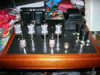
How about some pictures both inside and out.
Fill us in on the power supply details.. If you are using a full wave center tapped rectifier for B+ connect the center tap directly to the very first filter cap in the supply.
Hopefully your supply is sufficiently well filtered, (CLC?) the relatively low available loop gain and likely imperfectly matched output tubes probably means the PSRR is not all that high.
How about some pictures both inside and out.
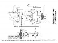
It is a floating paraphrase phase splitter and the cathodes are dc referenced through GNF to OPT secondary as pointed out. David Hafler is the constructor and it sounds very good. I have built it.
To kill hum totally I needed more farad on the second C then Hafler did. I used about 150 uF If I remember correctly. And be sure to ground both power and output transformer cores to chassies and power supply return. And depending on what you connect it to, one and only one of the devices shall have direct connection to earth ground.
To kill hum totally I needed more farad on the second C then Hafler did. I used about 150 uF If I remember correctly. And be sure to ground both power and output transformer cores to chassies and power supply return. And depending on what you connect it to, one and only one of the devices shall have direct connection to earth ground.
Last edited:
Also, the orientation of the output transformer(s) to the power transformer can allow induction of hum from power xfmr core to OPT core(s). The laminations of the transformers should be at 90-degree angle from each other, and not parallel or in line with each other.
OPT core - ==========
pwr xfmr core -
||
||
||
||
||
<---- front of chassis
OPT core - ==========
pwr xfmr core -
||
||
||
||
||
<---- front of chassis
Where is the secondary CT grounded? It should go straight to the negative end of the reservoir cap but it was quite common in the valve era to just ground it near the transformer and allow the charging pulses to find their own way via the chassis. A little bit of hum/buzz was regarded as normal in those days.
Thanks for all your suggestions so far. I've attached some pictures that might help. The power supply is a C-C-C-L-C. Both dual 50uf caps and the power supply transformer CT are grounded at the same point. Depending on mains voltage I have between 300 and 311 V DC. With .003-.010 ripple. Without an input signal the amp is dead quiet. With music from halfway up to full volume there is no buzz. Below that I get buzz. I'm using an 820 pico farad silver mica in the feedback circuit. The tubes are new JJ 12AX7's and the outputs are a NOS matched quad of Japanese made Magnavox 6V6's.
A buzz is a ground problem correct? I know 60 cycle hum and this isn't hum.
I would appreciate any ideas very much.
A buzz is a ground problem correct? I know 60 cycle hum and this isn't hum.
I would appreciate any ideas very much.
Attachments
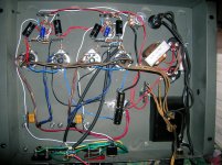
I see that the feed back resistor and compensation cap are located very far away from the input stage, this is a significant mistake - no guarantee that this will help fix this issue but for best performance this network should be right at the input tube socket.
Your volume pot is far too close to the choke and the power switch as well.
Filament wiring to the 12AX7A has large loops around the socket, take a look at the filament wiring sticky for some guidance on how to improve this.
Connect the high voltage secondary center tap directly to the capacitor lug, from there go to mecca ground.
Do not use the chassis as a ground path for the amplifier circuitry - no signal or power supply currents should flow through it!! Connect the mecca ground to the chassis - this should be the one and only point connected to chassis. (Other than the safety ground)
I can see you are using your chassis as a ground return and that the transformer is grounded to the chassis not the cap.
I often use romex for a ground bus.. Only one end is grounded and the supply ground is connected at this point. The bus is routed so as to provide a relatively short low impedance ground for everything connecting to ground.
Not too crazy about the input and OPT secondary grounds scheme, I would probably bring each back separately to the ground bus and ground them all together at the chassis end of the bus. (Sometimes it is helpful to tie the two rca grounds together and bring a single conductor back - I also recommend a 0.01uF ceramic cap from the ground side of the rca jack right to chassis at the jack for RFI.)
- Status
- This old topic is closed. If you want to reopen this topic, contact a moderator using the "Report Post" button.
- Home
- Amplifiers
- Tubes / Valves
- Dynaco low Power Amp