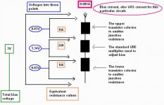
Those three resistances represents the internal resistances
offered by those transistors you have into the bias circuit.
Into the center, the 268 ohms represents the traditional VBE multiplier.... this means, all this circuit can be substituted by a fixed 268 ohms resistance, or 220 ohms, plus 47 ohms plus 1 ohm or other combination... this gonna do the statical job..not the dinamic job.
Upper you have the equivalent resistance you have into those other transistors, the upper auxiliary ones... resistance is 166 ohms.
Lower you have the equivalent resistance you have into those other lower transistors, the lower auxiliary ones, resistance is 166 ohms too.
All them together can be substituted by a 600 ohms fixed resistance or a trimpot adjusted to 600 ohms...will work fine, but only statically... will not have dinamic operation..will provide you , into my circuit, around 600 miliamperes of stand by bias and that is all it gonna do...also will feed current to the VAS...because they will cross this 600 ohms resistance sending current to the VAS. (observe Dx Amplifier schematic and things will be more clear)
A current of 5 miliamperes will cross those resistances, or the result you have adding one to the other (600 ohms)... and will develop 3 volts of bias... this voltage will be shared by four output transistors..and this will be plus 0.750V to the upper driver, plus 0.750 to the upper power transistor and negative 0.750V to the lower driver and negative 0.750V to the negative power transistor.
Into this circuit... the real circuit..the dinamic one, you have fixed the central resistance... the VBE multiplier will change its internal resistance value only because of heat generated and transfered to the transistor, or to the NTC.... the negative termistance... the resistance that reduces its value when hot.
Into this circuit... the real circuit... the dinamic one, you have non fixed extreme resistances... those ones will change value because they are transistors driven by the audio rectified captured into the output line... those resistances will reduce the value, to reduce the bias, when power is higher than a pré decided value stablished by the designer.... each diode will have 0.6 of voltage drop, and this will decide, together transistor junctions and auxiliary biasing resistances, the correct threshold voltage to switch from A to AB.
In the reality, this happens in a linear way...there is no switching behavior.... the resistance, those two extreme one, those two extreme transistors, goes reducing resistance obbeying the increasing of voltage sensed into the output line.. the more the voltage, the lower the resistance...inverse proportion there... of course within some limits that bellongs to the transistor minimum resistance when saturated... this is the lower limit of resistance.
I hope this is clear enougth to you folks.... at least i made strong efforts to make this clear.
regards,
Carlos
Attachments
Result fine dear Lumba.... there's a Brazilian Receiver that sold millions in this
country, and it is using exaclty this circuit with different resistances, adjustments, currents and threshold....it was very well accepted..sounds great (not perfect high end... i need more).
Was tested and aproved by all this country ears...so... the idea is tested...had industries using it, including JVC.
The problem is that you can use the hell thing to keep your coffee hot...it is a hell hot when iddle....or into low power (less than 5 watts RMS).... when you drive it hard it works into normal power amplifier temperatures.... around 50 degrees celsius into the heatsinks.
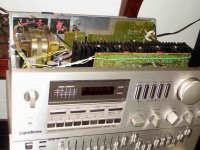
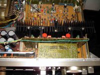
This one use the Super A circuit... alike the one i am showing you..can be installed into any amplifier.
This one is Gradiente, Model 1660, from the eigthies...sold millions and it is considered, now a days, one of the best ones made in this country for home use.
regards,
Carlos
country, and it is using exaclty this circuit with different resistances, adjustments, currents and threshold....it was very well accepted..sounds great (not perfect high end... i need more).
Was tested and aproved by all this country ears...so... the idea is tested...had industries using it, including JVC.
The problem is that you can use the hell thing to keep your coffee hot...it is a hell hot when iddle....or into low power (less than 5 watts RMS).... when you drive it hard it works into normal power amplifier temperatures.... around 50 degrees celsius into the heatsinks.
This one use the Super A circuit... alike the one i am showing you..can be installed into any amplifier.
This one is Gradiente, Model 1660, from the eigthies...sold millions and it is considered, now a days, one of the best ones made in this country for home use.
regards,
Carlos
Attachments
The risks where previously evaluated in advance my start into this idea
My problem is the mufled effect (i perceive, i think, my own subjective, personal evaluation about almost all class A amplifier) into the high frequencies.
This is what i have fear..about the circuit i am sure it works...because it is something used into industries.
regards,
Carlos
My problem is the mufled effect (i perceive, i think, my own subjective, personal evaluation about almost all class A amplifier) into the high frequencies.
This is what i have fear..about the circuit i am sure it works...because it is something used into industries.
regards,
Carlos
Attachments
I felt sad when increased my Dx Amplifier, the Standard one, bias
Became mufled.
This makes me thing.... should i continue or not?
Should i construct a Dx Standard and optimize (Optimus) to work into Class A and AB?
This is what i do not know...if i gonna loose my time or not.
What do you think folks?
regards,
Carlos
Became mufled.
This makes me thing.... should i continue or not?
Should i construct a Dx Standard and optimize (Optimus) to work into Class A and AB?
This is what i do not know...if i gonna loose my time or not.
What do you think folks?
regards,
Carlos
Attachments

Carlos,
Admittedly, I like the circlotron topology much more.
Nicer shirt, still no tie.
... proving nothing. Look, I don`t know, maybe the best way to find out would be adding it to an amplifier with known performance. Should give a clearly noticeable sonic improvement.there's a Brazilian Receiver that sold millions in this
Admittedly, I like the circlotron topology much more.
Nicer shirt, still no tie.
Proving nothing?..... 6 millions proves nothing?
This was five percent of the population...all them deaf?
Prove nothing?
Folks down here, in South America are clever too and can be so clever as your people... there are some folks with experience in audio too... if population accepts one brand and buy the brand in this quantity, even paying a really too high price for it, of course may be good.
Maybe you have more time to listen audio...say, Northern people, Nordic people, because you have a lot of time into the darkness..and this is good to listen music...but... other folks have ears too..we are all humans, there are not more the separation between Neanderthal and Cro-Magnon... we are darker because skin needs protection against the sun...melanine is the difference...the brain and ears are almost the same.
Bye dear Lumba...i will go to Orion for some monthes, when return i will call you once again.... i hope will met you less negative when return.
Be more happy!.... yes, maybe i misunderstood your point... i use to do those things..i do not know, even, to understand english very well.... or maybe you selected the text wrongly..had double meaning.
Fine Lumba... let it be....be happy.
Well... i was tweaking the HRII, increasing bias to 1 ampere each rail and i have perceived losses into high end.
Then i decided to tweak, and one of the modifications was the increase into the drivers current to share the "trouble" between those output folks...not to have the output one operating with 950 milivolts of VBE...not to have this!
Also i have reduced all capacitors to the feedback line, and the miller one till the threshold of oscilation..then i increase it a little.
Was reduced the input condenser to reduce the "effect" of deep basses that fool our perception a lot.. sometimes we feel we have not good treble..in the reality bass is dominating...old trick to reduce frequencies around 25 hertz.
Of course... i do not use anymore the treble booster you have into the HRII... this happened because my speakers...now a days this was fixed.
I found it better, the mufled effect almost have disappeared...BUT...this may be because i am biased about my amplifiers, in special this one that is lovely into treble range... i have to continue to listen and to call other guys to help me to evaluate this... and also to compare with other amplifiers...for a while i will rest a little.... it is too much hot to move.
It SEEMS it is less mufled.... i cannot guarantee.. this is a try to see if i can assemble the Optimus with variable bias...first of all to find solution to this mufling effect or give up.
Some pictures i have made while doing will be attached.
regards,
Carlos
Attachments
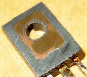
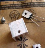
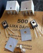
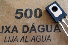
Use a glass, because it is the only guarantee surface we can have
Then place the sandpaper over the glass with grains atop.... sand the unit with attention to distribute the finger pressure into all front surface...not to put more strengh into one side compared to the other.
regards,
Carlos
Then place the sandpaper over the glass with grains atop.... sand the unit with attention to distribute the finger pressure into all front surface...not to put more strengh into one side compared to the other.
regards,
Carlos
Attachments
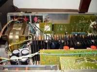
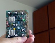
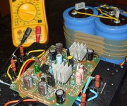
Yep... i am using double output pairs.
Emitter resistances are 1 ohms each one of them... there are some modifications made i will inform latter IF the amplifier result really good.
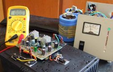
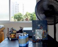
Now i have suspections on myself...you know.... we have spectations and this "washes our brain"...so.... i have to observe more and more... to listen more and more...to try other audio sources, other speakers.... there are many things to be done..and this takes time.
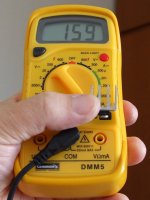
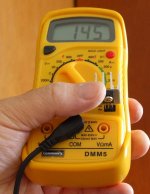
Wind is blowing...my poor supply dropped to 33 because 1 ampere each rail (bad supply)
Electrolitic condensers are 35 thousand each rail.
regards,
Carlos
Emitter resistances are 1 ohms each one of them... there are some modifications made i will inform latter IF the amplifier result really good.
Now i have suspections on myself...you know.... we have spectations and this "washes our brain"...so.... i have to observe more and more... to listen more and more...to try other audio sources, other speakers.... there are many things to be done..and this takes time.
Wind is blowing...my poor supply dropped to 33 because 1 ampere each rail (bad supply)
Electrolitic condensers are 35 thousand each rail.
regards,
Carlos
Attachments
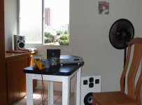
Wanna listen?
here you have a sample.... treble seems strong...have saturated the camera!
http://www.youtube.com/watch?v=eDXajPwqepQ
Now i have to fix the bass.
ahahahahh!
The old story.... we fix one side and other break.
regards,
Carlos
here you have a sample.... treble seems strong...have saturated the camera!
http://www.youtube.com/watch?v=eDXajPwqepQ
Now i have to fix the bass.
ahahahahh!
The old story.... we fix one side and other break.
regards,
Carlos
- Status
- This old topic is closed. If you want to reopen this topic, contact a moderator using the "Report Post" button.
- Home
- Amplifiers
- Solid State
- Dx Optimus is being prepared... dynamic bias.. Class A to AB