Thank you very much Alexandru (Alex mm)
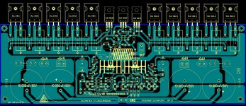
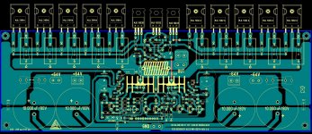
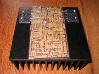
Nice board....and you have made it very fast, as usual.
Let's wait a couple of days to see if we gonna have interesting suggestions, it is already time to tweak a little as no one have ordered boards, so, modifications can be included in these board layout your are producing without too much sufferings to us.
I will soon have 60 years old, and this amplifiers celebrates my white hairs (almost white... in the reality they are gray), my losses of memory, my 50 kilos loss of weight and the operation i will make soon to remove the excesses of skin in my belly that resulted from the loss of weight.
I am glad health is perfect, blood examinations shown i am hundred percent healthy, also blood pressure, heart and all stuff operating perfectly... yes... every thing works here.... hehehehe.
Alexandru, what do you think to post the link of your nice amplifier?, the Goldmund clone video..the one that shows your home...or maybe you can think about to produce another custom one, showing only the Goldmund in details (close up or medium) if you think would be better.. you do not need to speak or use your language...image will be understood to the ones have the schematic..show us the nice machine you made while some interesting music can be playing in the background if you do not want to speak.... i want to give a try on it as you told it sounded very good... do not forget to send me your schematic, with your values and your transistors you have used.
Man!.... i do not know if is your camera audio recording quality.. for sure much better than the old stuff i have here, I felt the treble impressive and superior to the one i have achieved in my amplifiers.
regards,
Carlos
Last edited:
This amplifier has not lifted ground to input..you see
the input ground is the same ground you have in the output...the speaker terminal ground, called negative or black wire, is the same input ground, that is also the transformer secondary center tape... a system's ground.
I do think this may work better to lifted ground amplifiers alike the Dx Blame ST that has a 10 ohms resistance to the power ground...so...special input ground...in our MKIII Hx ground is the same...but no problems to make this way....if this may not help too much...also cannot be bad.
Thank you,
regards,
Carlos
yes , it will still work.
But not as good. Charging pulses of the large capacitors are quite big at the leads of that capacitor. With dual supplies and two exact width and length traces going to a center point is like 2 L/C filters to that point. At the center point the (pulses) tend to cancel each other out slightly... to a point. Add to this another 10R resistor plus the capacitance of the input stage component's .... this is another R/C filter. You are basically filtering your ground like you would do for your amplifier rails... and YOU can't say that is not important !
Another advantage to the resistor is that it will filter any RF or line noise (on the ground) from the sensitive input stage , the house ground return can pick up PC PS switching pulses , CFL's - as it is just a big antenna , as well. This is worse on a toroid trafo than an EI core. On both types of trafo's an AC line filter is a good thing to add. If the amp board has a separate power supply board , this is not all bad. The added wire has more inductance , but at the same time can pick up other "garbage" by the fact that it exists. So , some OEM's (and DIY'ers) put the cap's right on the main PCB. This is good provided that you isolate the sensitive VAS/input stage from them (pulses). Most OEM's will use larger local decoupling (R/C) and a better grounding scheme when this is the case.
Think of ground as yet another signal path , not 0v.
OS
the input ground is the same ground you have in the output...the speaker terminal ground, called negative or black wire, is the same input ground, that is also the transformer secondary center tape... a system's ground.
I do think this may work better to lifted ground amplifiers alike the Dx Blame ST that has a 10 ohms resistance to the power ground...so...special input ground...in our MKIII Hx ground is the same...but no problems to make this way....if this may not help too much...also cannot be bad.
Thank you,
regards,
Carlos
But not as good.
Charging pulses of the large capacitors are quite big at the leads of that capacitor. With dual supplies and two exact width and length traces going to a center point is like 2 L/C filters to that point. At the center point the (pulses) tend to cancel each other out slightly... to a point. Add to this another 10R resistor plus the capacitance of the input stage component's .... this is another R/C filter. You are basically filtering your ground like you would do for your amplifier rails... and YOU can't say that is not important !Another advantage to the resistor is that it will filter any RF or line noise (on the ground) from the sensitive input stage , the house ground return can pick up PC PS switching pulses , CFL's - as it is just a big antenna , as well. This is worse on a toroid trafo than an EI core. On both types of trafo's an AC line filter is a good thing to add. If the amp board has a separate power supply board , this is not all bad. The added wire has more inductance , but at the same time can pick up other "garbage" by the fact that it exists. So , some OEM's (and DIY'ers) put the cap's right on the main PCB. This is good provided that you isolate the sensitive VAS/input stage from them (pulses). Most OEM's will use larger local decoupling (R/C) and a better grounding scheme when this is the case.
Think of ground as yet another signal path , not 0v.
OS
Yes Josip, you can use them...i do think they will perform the same
I am not using them because i have not these transistors anymore...i love 2SC4793 and 2SA1837 ....i do think they are great....i love they are made of plastic, this way we do not need washers and insulators.
I could not test this amplifier with them...reason why i am not using them as standard...i would love to have some pairs of these lovely transistors...but i have not.....also my simulator does not have these ones...reason why i am using MJE15xxx series.
Use them Josip, and then inform us your results, your thoughts in a nice review with pictures and so on.
regards,
Carlos
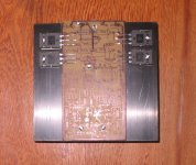
MKIII Hx performance at the simulator
numbers are not that bad...sonically it was approved... i am absolutelly sure you gonna love it....sonic signature emphasizes treble, despite the amplifier is absolutelly flat.
YouTube - MKIII Hx - performance at simulator.
regards,
Carlos
numbers are not that bad...sonically it was approved... i am absolutelly sure you gonna love it....sonic signature emphasizes treble, despite the amplifier is absolutelly flat.
YouTube - MKIII Hx - performance at simulator.
regards,
Carlos
I am developing a PRO version of this amplifier
But for different purposes than we have here..here is amateur, a DIY audio forum where sometimes non very skilled guys decide to build their first audio amplifier... i do not think we need to provide "hard to kill" amplifiers as this is not the purpose of this forum...seems to me it is for sharing experiences in an amateur way... well... DIY has this meaning to me.
I do not think we should increase cost with protections, or too much protections and publish these monsters here.... i do think people build to use at home, exception are some spies we have trying to capture schematics and them to produce amplifiers to sell in Ebay...but these are exception and not the rule.
Despite i dislike the sonic results of many of these protections, i am developing another MKIII, a hard to kill one... with clamp diodes, dumping resistances... VI limiters and also protected enhanced VAS, voltage regulator to the input circuitry and several other things in order to allow the guy to try to kill it if they want.... and i do think they will succeed installing and powering on the amplifier under water..or using a Caterpillar truck over it.
heheheheh...not for us.... i am amateur and i suppose this forum have not asked our degrees and documents showing we are Engineers or audio professionals.
regards,
Carlos
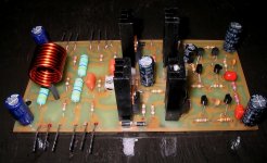
The differential pair, these two first transistors that receive signal and feedback
Are the most critical ones...but really do not bother yourself with off set.... an enormous off set of 200 milivolts means 5 miliwatts of energy you will waste..this does not move speaker and does not unballance power amplifier..let it be.
Usually, as standard, manufacturers accept values till 25 milivolts as normal, common, average and not problematic... obsessive guys sometimes worries too much about that... o hope you are healthy in your mind.
regards,
Carlos
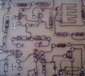
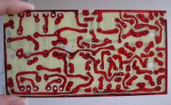
I do think i am getting old.... delaying to much to make an amplifier
in the past, 2 to 3 hours was all i needed to make layout, produce board, etch board, assemble and test...now a days i am spending this time only to produce board.
60 years is really old folks...uncle charlie now slow and lazy.
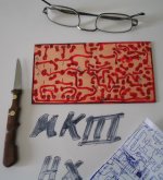
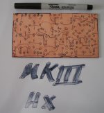
knife is to remove shorts in between tracks... we spend less time painting thick lines than trying to make them thin and perfect...time removing shorts is less than 5 minutes...so..we save time with the method.... the copper lines are made watching both board sides flipping it constantly, once a second...then you compare what is painted over and the need to trace lines to connect dots.
regards,
Carlos
in the past, 2 to 3 hours was all i needed to make layout, produce board, etch board, assemble and test...now a days i am spending this time only to produce board.
60 years is really old folks...uncle charlie now slow and lazy.
knife is to remove shorts in between tracks... we spend less time painting thick lines than trying to make them thin and perfect...time removing shorts is less than 5 minutes...so..we save time with the method.... the copper lines are made watching both board sides flipping it constantly, once a second...then you compare what is painted over and the need to trace lines to connect dots.
regards,
Carlos
Attachments
Last edited:
in the past, 2 to 3 hours was all i needed to make layout, produce board, etch board, assemble and test...now a days i am spending this time only to produce board.
60 years is really old folks...uncle charlie now slow and lazy.
knife is to remove shorts in between tracks... we spend less time painting thick lines than trying to make them thin and perfect...time removing shorts is less than 5 minutes...so..we save time with the method.... the copper lines are made watching both board sides flipping it constantly, once a second...then you compare what is painted over and the need to trace lines to connect dots.
regards,
Carlos
Why don’t jou use iron and laser print
- Status
- This old topic is closed. If you want to reopen this topic, contact a moderator using the "Report Post" button.
- Home
- Amplifiers
- Solid State
- Dx Blame MKIII Supercharged will soon be released