bonfis, I replaced the VAS for a 2SC1819 and the CCS for a 2SA1837. The drivers are still MJE15030 and MJE15031. The dent is still present, and when the baker clamp is absent, the sticking is also still there. The VAS and CCS replacement has changed nothing on the scope about these two behaviors.
In the VAS position, aside the MJE15030, I tried only the 2SC1819. I left it there as it's the best component for that role, in theory at least, with a Cob of 5pF.
In the CCS position, aside the MJE15033, I tried only the 2SA1837. I left it there as its specs are a closer match with the 2SC1819, although it's likely irrelevant...
These two guys changed nothing on the dent and rail sticking behavior.
In the drivers position, i tried:
- 2SA1930 & 2SC5171
- 2SA1837 & 2SC4793
- 2SA968B & 2SC2238B
All of these drivers gave approx the same result: the ringing that surfs on the positive sine wave, similar at what you had prior increasing base-stopper resistors. Remember that I have increased these to 100 Ohms on my circuit... These drivers all got rid of the dent going out of clip though... so, I guess I would need to adjust other values elsewhere if I want to keep 'em without ringing.
At the end, I'm back to square one, and I will accept that dent. I've replaced my clamping diode from a UF4004 to a NTE177, it's a BAV20 equivalent with a low TC of 5pF.
But because I've replaced the VAS with something theorically better, as a perfectly human human, I feel better now") hahaha (hi Carlos).
hahaha (hi Carlos).
I cannot pretend to hear any difference though.
I feel good about the amp. But I got to stop buying hard to find pieces, they're not cheap. The only drivers I would have love to try are Sanyos 2SA1011 & 2SC2344. But I feel that replacing these drivers will present the same result as the previously tried ones.
The amp is back in my listening room... I missed it while it was on my bench...
Mart.
In the VAS position, aside the MJE15030, I tried only the 2SC1819. I left it there as it's the best component for that role, in theory at least, with a Cob of 5pF.
In the CCS position, aside the MJE15033, I tried only the 2SA1837. I left it there as its specs are a closer match with the 2SC1819, although it's likely irrelevant...
These two guys changed nothing on the dent and rail sticking behavior.
In the drivers position, i tried:
- 2SA1930 & 2SC5171
- 2SA1837 & 2SC4793
- 2SA968B & 2SC2238B
All of these drivers gave approx the same result: the ringing that surfs on the positive sine wave, similar at what you had prior increasing base-stopper resistors. Remember that I have increased these to 100 Ohms on my circuit... These drivers all got rid of the dent going out of clip though... so, I guess I would need to adjust other values elsewhere if I want to keep 'em without ringing.
At the end, I'm back to square one, and I will accept that dent. I've replaced my clamping diode from a UF4004 to a NTE177, it's a BAV20 equivalent with a low TC of 5pF.
But because I've replaced the VAS with something theorically better, as a perfectly human human, I feel better now
hahaha (hi Carlos).I cannot pretend to hear any difference though.
I feel good about the amp. But I got to stop buying hard to find pieces, they're not cheap. The only drivers I would have love to try are Sanyos 2SA1011 & 2SC2344. But I feel that replacing these drivers will present the same result as the previously tried ones.
The amp is back in my listening room... I missed it while it was on my bench...
Mart.
Last edited:
Hi Mart
I'm glad you're back to listening. For my part the cover is back on my MK III and likely to stay there. The sound quality is very satisfying and I don't see any obvious prospects for improving it. Should you to get the bug to be back at the bench and there happen upon a modification of merit please let me know. In the interim my best to you and thanks to all the builders and contributors to this most varied and interesting thread.
Steve
This is an attractive amp to build and I have a few questions if anyone can answer them so I do not have to search the entire two years of posts.
What is the wattage on this amp? Did I read 150 watts per channel?
How does it sound? I think I read where Carlos stated it sounded glorius but say you?
Carlos thank you so much for making your design available to the world.If not for guys like you,guys like me would have nothing to build.
What is the wattage on this amp? Did I read 150 watts per channel?
How does it sound? I think I read where Carlos stated it sounded glorius but say you?
Carlos thank you so much for making your design available to the world.If not for guys like you,guys like me would have nothing to build.
The maximum output power depends on the load impedance you drive and the power supply rail voltage.
There is no single maximum power for this, nor any amplifier.
You choose how to implement the build.
You could end up with anywhere between 40W and 300W depending on who you believe and how you assemble.
There is no single maximum power for this, nor any amplifier.
You choose how to implement the build.
You could end up with anywhere between 40W and 300W depending on who you believe and how you assemble.
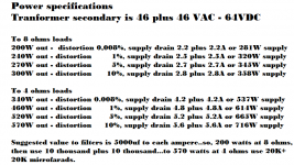
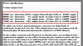
Here you have power specifications
This depends on your supply voltage...was measured in the simulator and there the voltage do not drop.
Real world you have voltage drop and will not achieve all that power.
To achieve you must have stable voltage, this depends on SMPS or a series pass regulator that will have higher voltage at the regulator input.... doing this way, having stable voltage when loaded, then you will achieve this power shown in the chart.
Carlos
Attachments
Last edited:
Yes.... the amplifier can drive 3 ohms loads....can drive even 2 ohms
but cannot drive lower than that.
Impedance depends on the speaker impedance graphic.... you should check if it goes below 3 ohms in some frequency.... sadly they usually go lower...and this is dangerous.
If it is really 3 ohms and do not reduce the impedance in any frequency..them no problems.
In the real world it may have valleys of impedance, and 3 ohms is just nominal and at 1 Kilohertz only.
regards,
Carlos
Hello all,
I have read this thread from start to finish and have learnt a lot from other peoples experiences.
My only decision still to make is what output transistors to use. I will only be using 4 output pairs due to space.
I have come down to a short list of two the MJL1302/3281 pair of the MG6331-R/ Mg9412-R. Both have similar specs. I prefer these over the MJL4302/MJL4281 pair due to PNP and NPN Hfe matching and the linearity.
What do people think?
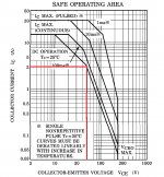
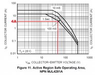
Please...for safety reasons, use MJL4281A
Watch the S.O.A and you will see that it can hold more current when operating 55 or 65 volts compared to the most common competitor.
In special this advice is for you, because you will use only a few transistors.... do not use 2 ohms...use only 8 and 4 ohms loads if your supply is the suggested or lower voltage...if higher..then use only 8 ohms.
In this video you can see a picture of a beautifull Blame MKIII Hx:
http://www.youtube.com/watch?v=HoTMMsrr20U
regards,
Carlos
Attachments
Last edited:
Carlos,
Thank you for the reply. I know you go on about perception. Is a case of perception when it comes to choosing output devices regarding sound.
Fortunately, I have the MJL4281 pair in my components box the I obtained as samples a few years back. I shall be building this amp at the weekend.
There are bigger more powerful devices available from semelab but if the datasheets are to be believed they appear to have sacrificed speed and linearity for output current. Also, not sure if I believe you can have a 400W device in a TO3P package.
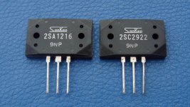
Want high end...want shinny treble..then use Sankens
here you see a beautifull MKIII Hx at one minute exactly.
I am not sure if Sankens will fit in this pcboard...maybe not...but for treble they are the best.... others are all almost the same...small differences.... MJL4281A looks to produce nice bass.... but this may be my imagination only.
I am using these transistors into my PC monitoring amplifier...the treble cuts the air alike a razor..alike a lash of a whip... fast and precise....lovely sound.
Be happy! - alegria não tem preço - YouTube
regards,
Carlos
Last edited:
Shiny treble. Yes, that is what I'm after. Sanken must have something in the T03P or TO264 package that would be suitable. I'm willing to sacrifice some of the brute power for SQ.
Not too concerned with bass since the plan is to use the amps in a 3 way active setup with equalised sub woofers. Currently I have leach amps running and fancy a change.
Research will commence.
Not too concerned with bass since the plan is to use the amps in a 3 way active setup with equalised sub woofers. Currently I have leach amps running and fancy a change.
Research will commence.
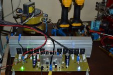
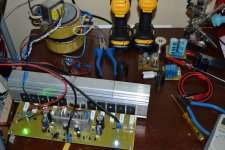
My Old DX MKIII been modified and here's the new look
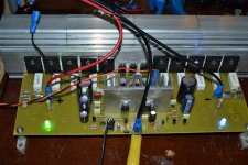
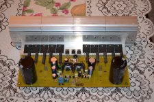
I really like the performance of this amp in terms of Power, Bass, Mid and treble, but when I try to fix inside the box I realize there is no enough space on the box if the output transistors are in horizontal position, and the VAS transistors are very hot, I try to install a big heat sink but I’m not happy if the heat sink is not mounted on the board, I feel the leads of the transistor will not last long, so I decided to make a little modification base on Alexmm layout to suit my needs, now this amp is perfect for my needs, now temp on VAS transistor are stable even without cooling fan. Very cool amp I really like it…..
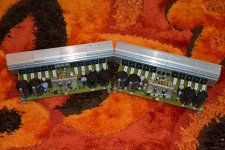
Below you can see the image before (in horizontal output) and after modification it's in vertical position with adequate heasink in VAS transistors the remaning are the big caps to finish my 1st channel, now this amp is singing with +/-80VDC.
My next step is to assemble the second channel to drive my subs together with my DX Super A …..
Regards,
I really like the performance of this amp in terms of Power, Bass, Mid and treble, but when I try to fix inside the box I realize there is no enough space on the box if the output transistors are in horizontal position, and the VAS transistors are very hot, I try to install a big heat sink but I’m not happy if the heat sink is not mounted on the board, I feel the leads of the transistor will not last long, so I decided to make a little modification base on Alexmm layout to suit my needs, now this amp is perfect for my needs, now temp on VAS transistor are stable even without cooling fan. Very cool amp I really like it…..
Below you can see the image before (in horizontal output) and after modification it's in vertical position with adequate heasink in VAS transistors
the remaning are the big caps to finish my 1st channel, now this amp is singing with +/-80VDC.My next step is to assemble the second channel to drive my subs together with my DX Super A …..
Regards,
Attachments
Last edited:
excellent
very nice work, very nice work,hermoso acabado
I really like the performance of this amp in terms of Power, Bass, Mid and treble, but when I try to fix inside the box I realize there is no enough space on the box if the output transistors are in horizontal position, and the VAS transistors are very hot, I try to install a big heat sink but I’m not happy if the heat sink is not mounted on the board, I feel the leads of the transistor will not last long, so I decided to make a little modification base on Alexmm layout to suit my needs, now this amp is perfect for my needs, now temp on VAS transistor are stable even without cooling fan. Very cool amp I really like it…..
Below you can see the image before (in horizontal output) and after modification it's in vertical position with adequate heasink in VAS transistors
My next step is to assemble the second channel to drive my subs together with my DX Super A …..
Regards,
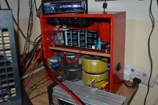
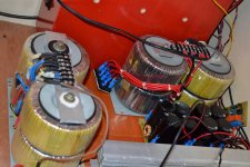
Wow, do you have enough transformers?
Wow, do you have enough transformers?
Those 8 boys are enough to do their job....
8 X 28VAC / 300VAC each...
Attachments
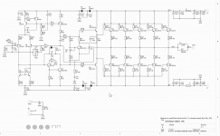
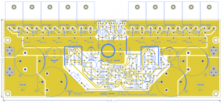
My try at a PCB
Thanks DX and the rest of the community for a very interesting project.
Here's my try at a PCB. It takes much inspiration from the very nice official layout by Alex MM. I just wanted to have some fun trying my hand at it.
* It is slightly narrower at 10 inchces (254mm) vs. 265 mm to accommodate my anticpated heat sink which is only 10 inches wide
* The zobel inductor is intendend to be mounted with the axis of winding perpendicular to the board
Question:
The recommended voltage is +/- 64V. If one had a 50v transformer giving a rectified voltage of about 72v, would that cause a problem?
Attachments
- Status
- Not open for further replies.
- Home
- Amplifiers
- Solid State
- Dx Blame MKIII-Hx - Builder's thread