But i really would like you to make your own Juan
To make alike the Dx Super A...that resulted beautifull...just use the shape Alex mm made... resulted good... despite i do not like long boards this way....long strip boards...but it is looking good.
Use condensers the way Alex did, and was made this way to fill the empty spaces, the clearances there.... all surrounding is standard...power transistors are the same in zillion of designs..but your style to the Dx Super A applied to this amplifier will be good.... say...to the center core of the layout...the audio amplifier itself but the output..then will be great.
And beeing your the design, from the scratch, you may be rid of these comments.
I am having people asking for this design in Brazilian foruns...you may have some orders if you make it.
regards,
Carlos
I think you are correct, is better from scratch it take longer but at the end will be a complete different design I will try to make it more like the Dx Super A style we all see how is going to end maybe smaller or a bit larger we really don't know because according to your format specifications it take more time, alignments, parts no so close each other, letter fonts all the same, space between transistors the same, is not easy but with lot of patience I can do it why not I don't have noting to lose anyway lol  jejejejejejej
Regards
Juan
jejejejejejejRegards
Juan
Attachments

Last edited:
Just discovered that the thread has come alive again. The modifications contemplated by Cannonica were implemented in my Mk III when I observed instability after attempting to increase the quiescent bias. I found that an 56R base stopper completely eliminated the instability and allowed the bias to be increased to 57mv. per pair. This in turn substantially reduced measured THD. A further reduction was achieved by increasing the feedback ratio (and reducing closed loop gain). My amp has a gain of approximately 25 which is adequate for a system using a preamp but on the low side for those driving the amp with mp3 players. I'm also interested in reducing Cdom further (currently at 180pf) to improve slew rate. Look forward to hearing about the results of Cannonica's experiments.
I was also wondering about the zobel network comprised of the 47nF cap and 15R resistor... Some bias induced oscillations can be dampened by this, but the values used doesn't seem to be optimal (no pun intended to the designer) . The optimal values is more around 100nF and 10R. the higher cap will pass-on lower frequencies oscillations while the 10R resistor will dampen it more. In "standard" designs "default" values always seem to be 100nF and 4.7R-10R for the resistor (never higher than 10R as per Dr. Self) ...
I may start modifying those two components first to see if it gets rid of the high-biased oscillations observed by me (and bonfis).
Martin.
It is a pity that there is spoken about "different amps and boards", "I think" it belongs in a other topic.
So this topic Dx Blame MKIII-Hx - Builder's thread becomes a mess.
Carlos opened this topic, so he is the boss and decides what to do ...
Martin and Bonfis you both do a great job, to get this amplifier to a higher level.
Regards,
Rudy
So this topic Dx Blame MKIII-Hx - Builder's thread becomes a mess.
Carlos opened this topic, so he is the boss and decides what to do ...
Martin and Bonfis you both do a great job, to get this amplifier to a higher level.
Regards,
Rudy
Other kind of layout BMW....another type of layout
Not really another amplifier... this same amplifier with a different pcboard with other "decoration" you know?
Also i am not the boss my dear.... if i was the boss i would say:
- "Do not mess with my amplifier"
And i did different, i said:
- "Try by yourself to make it even better"...and i also cooperate with all of you trying to.
I would love if i ever have a boss this way man!
regards,
Carlos
Last edited:
I was also wondering about the zobel network comprised of the 47nF cap and 15R resistor... Some bias induced oscillations can be dampened by this, but the values used doesn't seem to be optimal (no pun intended to the designer) . The optimal values is more around 100nF and 10R. the higher cap will pass-on lower frequencies oscillations while the 10R resistor will dampen it more. In "standard" designs "default" values always seem to be 100nF and 4.7R-10R for the resistor (never higher than 10R as per Dr. Self) ...
I may start modifying those two components first to see if it gets rid of the high-biased oscillations observed by me (and bonfis).
Martin.
Hey Martin-
I think the zobel might very well be adjusted to damp the parasitics. Mine has the standard values but it did not prevent the oscillation from being present at the output. My suggestion would be to try and eliminate them at the source. The stopper resistor change accomplished this nicely with minimal fuss. Before the change high freq oscillations (a few Mhz) were visible on my scope riding the peaks of a 1 Khz sine wave that was driving the amp. Once the stoppers were increased these disappeared at all power levels and all bias settings. If you don't have a scope this is a leap of faith kind of change. However if you notice that bias voltage changes suddenly as you try to adjust it upward there's a good chance you've got the oscillation too. After making the stopper change bias can be increased smoothly with no sudden jumps up to and beyond 56 mv across 2 emitter resistors. That should be all the evidence you need to feel confident that you tamed the beast.
Good Luck
Steve
Thanks bonfis for the advice. Also in simulator, tampering with the zobel doesn't change anything about the + side ringing.
I have the necessary components, need some time now to execute. As you mentionned, my only indicator is a sudden jump in bias voltage when adjusting.
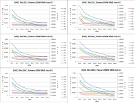
As a bonus, here are the distortion figures for 3 values for base-stoppers and for vBias from 2mV to 66mV. As demonstrated, changing the stopper values does not much on the harmonics behavior, but increased bias can reduce odd harmonics significantly but more importantly: below even order ones...
Again vBias is measured between the TWO emitter resistors. The Magnitude scale on left refers to the harmonics while the right scale is exclusively for THD. Left and right scales are NOT related, I just wanted the THD to be present on the same graph.
Regards,
Mart.
I have the necessary components, need some time now to execute. As you mentionned, my only indicator is a sudden jump in bias voltage when adjusting.
As a bonus, here are the distortion figures for 3 values for base-stoppers and for vBias from 2mV to 66mV. As demonstrated, changing the stopper values does not much on the harmonics behavior, but increased bias can reduce odd harmonics significantly but more importantly: below even order ones...
Again vBias is measured between the TWO emitter resistors. The Magnitude scale on left refers to the harmonics while the right scale is exclusively for THD. Left and right scales are NOT related, I just wanted the THD to be present on the same graph.
Regards,
Mart.
Attachments
I found that an 56R base stopper completely eliminated the instability and allowed the bias to be increased to 57mv. per pair. This in turn substantially reduced measured THD.
Something I'm not understanding,
You say that with a low base stopper (whose function is to 'stop' oscillation) the output shows ringing on a real ciruit.
But when increasing the base stopper value to >= 56R it completley eliminates the instability,
I agree this is true, base stoppers doing there job.
But then I'm confuced that you say that "This in turn substantially reduced measured THD"
Did you really measure the THD or just simulate for it.
I can't believe that a output full of ringing has less THD than an output with no ringing.
Personally a Bias of 30mA +/- 5mA per output device is enough for me
Regards
Yes, any Member can open a topic. No, that does not make the Thread opener the "boss"...........................Carlos opened this topic, so he is the boss and decides what to do ..................
The Thread opens the door to all Members that want to make a comment or observation.
Every Member has the right to contribute to ANY Thread.
the purpose of the base stopper is two fold......................You say that with a low base stopper (whose function is to 'stop' oscillation) the output shows ringing on a real ciruit...................
1.) it adds a real resistance to the load seen by the previous stage. If the load without the base stopper is real and +ve, then the stopper just adds some resistance.
if the load is a -ve resistance then the stopper can and should make the source see a +ve resistance load, i.e. converts the load from -ve to +ve, if the Rb is selected big enough.
2.) the stopper when very close to the base junction reduces the inductance seen by the junction and the parasitics around that junction that can create an oscillator if an uncontrolled inductor is attached to that base lead.
I am very unskilled at this AC circuit theory, so I hope what I have stated above is close to fact.
I welcome anyone to correct any errors I have stated above, or to reword either of my two statements to make them technically more accurate.
the current value of the output bias is irrelevant to a ClassAB amplifier........................ a Bias of 30mA +/- 5mA per output device is enough................
The important value is Vre.
This is discussed and explained at length in many Threads by many Members. It is detailed in D.Self's papers and by Cordell and many other renowned amplifier Designers.
Set the output stage to optimal ClassAB bias, using the "voltage" method described by Self, both in his amp design books and in the web pages of his site.
Something I'm not understanding,
You say that with a low base stopper (whose function is to 'stop' oscillation) the output shows ringing on a real ciruit.
But when increasing the base stopper value to >= 56R it completley eliminates the instability,
I agree this is true, base stoppers doing there job.
But then I'm confuced that you say that "This in turn substantially reduced measured THD"
Did you really measure the THD or just simulate for it.
I can't believe that a output full of ringing has less THD than an output with no ringing.
Personally a Bias of 30mA +/- 5mA per output device is enough for me
Regards
It was the increased bias that reduced THD. Before changing the stoppers I noticed (as have other builders) that oscillation would start when the bias was increased beyond a certain point (I don't recall the exact voltage). I never measured the THD while the circuit was ringing but I agree it would have been quite high.
After inserting the 56R stoppers I measured THD as I adjusted the bias upward. THD came down steadily until about the 60 mv point (measured across 2 emitters) where it pretty much leveled off. THD was reduced to about 10% of the amount measured at the recommended bias setting.
I don't have a personal preference on bias I just follow the procedure of adjusting for minimum THD. My heat sinks seem to handle the idle current just fine so I'm happy.
Steve
crossover distortion should be at a minimum when Vre~50mV when Re=0r47........................ as I adjusted the bias upward. THD came down steadily until about the 60 mv point (measured across 2 emitters) ....................e
As Re goes down, Vre also goes down. This is because the internal resistance of the transistor becomes a higher proportion of the total emitter resistance. Optimal ClassAB biasing uses the voltage across the "external" emitter resistor. The "internal" emitter resistance cannot be measured by the Vre method.
D.Self details this.
I finally neglected my family, friends and responsibilities for a few hours and proceeded with the modifications
Here what i've done:
Replaced the 22 Ohms base-stoppers with 100 Ohms.
Replaced the 180pF miller cap with a 100pF one.
Increased the bias to 54mV cold (across both emitter resistors).
Yes the high-bias stability was restored by increasing the base-stoppers as expected and as witnessed by bonfis.
I did all of this with a lot of precautions. I started it first with resistors in place of the fuses and using the light-bulb in serie with the power cord.
I did only one channel to be able to do an A-B comparison.
If you do this mod and increase the bias, make sure you won't have cooling problems. Sitting idle for around 60 minutes, the heat-sink temperatures are 27C for the unmodified channel (4mV bias) and 37C for the modified one at 54mV bias.
No adjustment is required concerning the DC offset, it hasn't changed.
Now about the subjective impressions... I did only 30 minutes worth of comparing. I used recordings that are not overly compressed, 12-14dB worth of dynamics and some that only has 5-6dB of dynamics.
As of now, I noticed pleasant differences. I will try to describe what I listened so it's hard to explain. And no i didn't do any double-blind tests as I don't personnally consider this necessary.
The sound... or sonics as some says...
The first thing that stands out is the slight attenuation of the middle-mids and high-mids. Like in the voice, electric guitar, snare range, they're less proemininent. On the unmodified channel, they tend to crush everything around them. Now they're more evenly blended.
The second thing I noticed is an increase of clarity and definition of the highs. The cymbals are back and have a clearer sustain and brillance. It's probably due to the fact that they're not sent backwards by the middle-mids and high mids registers.
Also the bottom end, the "roundness" of the sound is increased slightly.
I would say that an better separation is listenable between the instruments because of the lack of confused (or confusing?) mids.
Overall theses mods are keepers. Since I don't have a scope (yet??) I cannot confirm if any rigning or oscillations is present. But for sure, my listening observations correlate what was expected by lowering the odd-order harmonics (through increased bias).
Some will probably say my observations are irrelevant because I always know which channel is playing and blahblahblah... too bad for them, they need to do that mod and test it by themselves then
I think that it's a matter of taste, I guess some will prefer without the mods, some will prefer as modified and some others will need to have an in-between solution.
I listened to that amp for a whole year as of now. I'm gonna modify the other channel and reinstate it its normal environment. Time will tell if it's a long-term keeper or if it's only an over-optimistic mod.
If you feel comfortable doing this mod, please do so and share your impressions.
Martin.
the purpose of the base stopper is two fold.
1.) it adds a real resistance to the load seen by the previous stage. If the load without the base stopper is real and +ve, then the stopper just adds some resistance.
if the load is a -ve resistance then the stopper can and should make the source see a +ve resistance load, i.e. converts the load from -ve to +ve, if the Rb is selected big enough.
2.) the stopper when very close to the base junction reduces the inductance seen by the junction and the parasitics around that junction that can create an oscillator if an uncontrolled inductor is attached to that base lead.
I am very unskilled at this AC circuit theory, so I hope what I have stated above is close to fact.
I welcome anyone to correct any errors I have stated above, or to reword either of my two statements to make them technically more accurate.
In the same way that the emiiter impendance is "seen" by the base, so to is the base impedance seen by the emitter.
Thus in adjusting for optimal bias high value base stoppers should reduce the desired measured drop across the the external resistors.
Thanks
-Antonio
I'm not as experienced as most here with audio,
But sadly its been my experience that my original expectations from design, don't match my final circuit in 'real world conditions'.
For example, my last amplifier simulated at 0.001% THD 1-30kHz at 185W into 8R.
So expectations were high, then I build the prototype and .... hehe problems.
I also had to increase base stoppers, rather than increasing miller cap, or reducing gain. and make a number of small changes, all which took me further away from my expectations.
My result for now is a amp that I like the sound of, and I guess thats what matters,
Regards
Wow,
Thanks for taking the time to provide us with these updates Martin , very valuable input, now i have starting point ....
Thanks for taking the time to provide us with these updates Martin , very valuable input, now i have starting point ....
I finally neglected my family, friends and responsibilities for a few hours and proceeded with the modifications
Here what i've done:
Replaced the 22 Ohms base-stoppers with 100 Ohms.
Replaced the 180pF miller cap with a 100pF one.
Increased the bias to 54mV cold (across both emitter resistors).
Yes the high-bias stability was restored by increasing the base-stoppers as expected and as witnessed by bonfis.
I did all of this with a lot of precautions. I started it first with resistors in place of the fuses and using the light-bulb in serie with the power cord.
I did only one channel to be able to do an A-B comparison.
If you do this mod and increase the bias, make sure you won't have cooling problems. Sitting idle for around 60 minutes, the heat-sink temperatures are 27C for the unmodified channel (4mV bias) and 37C for the modified one at 54mV bias.
No adjustment is required concerning the DC offset, it hasn't changed.
Now about the subjective impressions... I did only 30 minutes worth of comparing. I used recordings that are not overly compressed, 12-14dB worth of dynamics and some that only has 5-6dB of dynamics.
As of now, I noticed pleasant differences. I will try to describe what I listened so it's hard to explain. And no i didn't do any double-blind tests as I don't personnally consider this necessary.
The sound... or sonics as some says...
The first thing that stands out is the slight attenuation of the middle-mids and high-mids. Like in the voice, electric guitar, snare range, they're less proemininent. On the unmodified channel, they tend to crush everything around them. Now they're more evenly blended.
The second thing I noticed is an increase of clarity and definition of the highs. The cymbals are back and have a clearer sustain and brillance. It's probably due to the fact that they're not sent backwards by the middle-mids and high mids registers.
Also the bottom end, the "roundness" of the sound is increased slightly.
I would say that an better separation is listenable between the instruments because of the lack of confused (or confusing?) mids.
Overall theses mods are keepers. Since I don't have a scope (yet??) I cannot confirm if any rigning or oscillations is present. But for sure, my listening observations correlate what was expected by lowering the odd-order harmonics (through increased bias).
Some will probably say my observations are irrelevant because I always know which channel is playing and blahblahblah... too bad for them, they need to do that mod and test it by themselves then
I think that it's a matter of taste, I guess some will prefer without the mods, some will prefer as modified and some others will need to have an in-between solution.
I listened to that amp for a whole year as of now. I'm gonna modify the other channel and reinstate it its normal environment. Time will tell if it's a long-term keeper or if it's only an over-optimistic mod.
If you feel comfortable doing this mod, please do so and share your impressions.
Martin.
Vostro
I think simulators are great, and in your case can't you go back and add inductance to the base of the output transistors, and some load capacitance, possibly collector inductance as well to best match the observed parasitic oscillation?
Imagine trying to do even very simplified analysis by hand, simulators can get you there but they need to be refined as you extract new infromation from the working circuit (or simplified if you are just trying to understand).
Thanks
-Antonio
- Status
- Not open for further replies.
- Home
- Amplifiers
- Solid State
- Dx Blame MKIII-Hx - Builder's thread