Thank you Junie, in Brazil we speak portuguese
muchas gracias senhor Carlos is spanish... in portuguese is
- "muito obrigado senhor Carlos"
Meaning in english is:
- "thank you Mr. Carlos"
But we can understand.... latine languages are easy, Italian, French, Spanish and Portuguese have the same root.
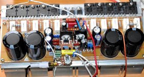
A picture from other forum, another MKIII Hx playing loud and clear.
regards,
Carlos
muchas gracias senhor Carlos is spanish... in portuguese is
- "muito obrigado senhor Carlos"
Meaning in english is:
- "thank you Mr. Carlos"
But we can understand.... latine languages are easy, Italian, French, Spanish and Portuguese have the same root.
A picture from other forum, another MKIII Hx playing loud and clear.
regards,
Carlos
Attachments
Last edited:
Do you want to hear about the correct way to adjust the bias of DX amplifiers?
I'm all ears ...........
")
Thank you Andrew
That's a lot of instructions, but worth following!
I have one more question for Carlos, or anyone else who knows the answer. I'm using a 56.4V power supply. Should I set the voltage drop across the 100ohm resistor to -4.4V, as I would with a 64V supply? Or should I calculate
64V : -4.4V = 56.4V : -3.88V
and set the voltage drop across the setup resistor to -3.88V?
2SC5200/2SA1302 is compatible with this amp right?
Hey Boscoe, I'm using 2SC5200/2SA1973 OP at the moment, so far so good. been running two hour and no heat build-up yet...or maybe not.
Byron... will be better to adjust monitoring power emitter resistances
in order to measure a voltage drop of 1 milivolt or a little bit less into one of the power transistors .... others will be reasonable too.... try to measure in one of your transistors that are in the positive side, the NPN transistors, as they have lower gain and this way your PNP will be fine with a little bit higher current in stand by mode.
1 milivolt measured over (voltage drop in DC milivolts, 200 milivolts scale) a 0.47 ohms resistor represents a current of 2.1 miliamperes...and this multiplied by your voltage from colector to emitter says you will be dissipating 118 miliwatts in each one of them.... so... 10 transistors may dissipate 1 to 1.5 watts (because PNP will dissipate more, the gain is bigger, the current there will be bigger, so the dissipation).... this is 21 miliamps in the output transistors, you have CCS sucking current too, but you should not worry too much, because if you have low offset and bias control trimpot adjusting the current means your amplifier is fine....this way go monitoring your output current in one of your transistors and everything gonna be all right.
If you dislike the method, despite i am saying it is the best way to keep things cool, then try 10 volts over your 100 ohms protective resistor and let it be this way (less cool, more heat).
I am suggesting this way because i know that people will never use the heatsinks in the size i suggest, so, people may face problems of heat due to small heatsinks (more elegant, more pretty, smaller represents smaller price too... but they are less efective) and adjusting with the smallest possible current in the output, you will be rid of some heat, not only in stand by mode but also during dinamic operation as you will change your operational point.
My suggestion to heatsinks is an aluminium blade of 4 by 4 inches (square) to each 10 watts.... power will depend your distortion, supply current, supply voltage and speaker impedance... each one will have a different case..... so, if your will operate 100 watts each channel, then you will need the equivalent of 10 blades to each channel if external heatsinks..if internal you should increase 50 percent the size...if use a blower you can use half the heatsink size....if you use more than one blower and tunnel ventilation, then your efficiency will be multiplied by 4 (minimum)... and heatsink size will reduce in the factor of 4 too.... this is for heavy duty..if you will use music...or a non constant tones being amplified (unlike pipe organ) .... then you will have twice the efficency and 10 by 10 centimeters (4 by 4 inches) will be good to 20 watts...... so, two blades will be good for 40 watts... three blades for 60 watts RMS.... the equivalent you know.
I hope i was clear..if not, then ask again.
regards,
Carlos
Last edited:
About excessive heat in the vertical heatsinks
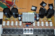
MJ777 from another forum tried two different solutions, the first one was increasing the heatsink size that resulted fine, temperature dropped to 42 degrées celsius (human fever).
He tried a second solution installing these transistors below the pcboard, this way they were screwed into the main heatsink and temperature result fine too.
regards,
Carlos
Attachments
What PSU voltage is he running the MK3 with Carlos ...?
Words from the initial poster on foreign forum:
I'm using a rail voltage of plus/minus 68 volts dc from a 50-0-50 volts ac transformer rated 10 amperes.
People that feel these 2 small vertical heatsinks too much hot can reduce VAS current in order to reduce heat there.... i have simulated and i found the original schematic fine... with the modification you will have changes in performance, but not that huge.
The 22 ohms resistor that sets the CCS current can be increased to 47ohms in order to reduce current...then you will have these transistors mounted into vertical heatsinks (CCS to VAS and VAS transistor) less hot.
I found power there not that big...the left one is the CCS transistor, CCS to feed VAS (Voltage Amplifier Stage) and it is dissipating 1.65 watt.... the rigth side one is the VAS transistor, the second stage, the most active unit, following the buffer and the power there, dinamic power, will be around 1 watt....not that huge power and the small heatsinks should fit in most of the cases... exception is when people is using higher supply voltage... say... really higher voltage.
You can replace the 22 ohms resistor by a 27 ohms, 33 ohms, 39 ohms or 47 ohms.... i suggest you to go to 47 ohms because will really cool down in order to work fine with tiny vertical heatsinks... with this resistor replaced, the performance when using low impedance output loads will clip earlier.... some loss in power...not that huge, not that important.
Carlos
Hello dear Carlos,
Do you have an estimate on how much less the dissipation would be with a 47R? And do you have the power and distortion figures when using that resistor value?
If you recommend this, I assume you have evaluated that the sonics will remain the same?
Thank you,
Martin.
Attachments
Words from the initial poster on foreign forum:
Thanks ...
Maybe it's better to use bigger heatsinks than reduce CCS current ... ?
Yes....better to increase heatsinks than to reduce current
As i said.... audio is almost the same...not the same.... while operating high current (low impedance) we have losses when we reduce current increasing that resistor to 47 ohms...it is an option...but not the best option...better is to increase heatsink size.
regards,
Carlos
As i said.... audio is almost the same...not the same.... while operating high current (low impedance) we have losses when we reduce current increasing that resistor to 47 ohms...it is an option...but not the best option...better is to increase heatsink size.
regards,
Carlos
-48 volts into the VAS transistor emitter and -922 milivolts into the VAS colector
This is achieved using a 50 Volts supplies.... was the voltage i found the amplifier better sonically...but was not optimized into THD measurements, despite the difference (numbers) was not important.... this voltage was achieved with a 55 volts supply ... when driving the amplifier hard to full power (so, dinamically operating) the supply voltage was dropping to 50..and there was the point it was lovely.
Will it be worse with other voltages?
Not really Wayne, and you wanna know why?..... because you having not listened the unit with 50 volts you will not know how it can perform while operating with this voltage.....and not knowing you will never know....not listening you will not perceive...it is not that easy to perceive...sometimes i have to repeat tests to perceive...difference is so small that sometimes i feel i am crazy.....well....maybe i am.
Using 45 volts supplies you will be working fine too, do not worry too much because this amplifier sounds lovely anyway...hard to kill the sonics...even making mistakes and foolishes i found it always fine.... watch carefully, you will see the Blameless from Doctor Self there...basically it is a Blameless..the topology is almost the same..some touches and retouches, some fine tuning, tips and tricks applies and was listened carefully and tweaked for sonics..but basically..you have the best possible design ever made (till today) by Doctor Self...he made other designs...i tried some...no one (to my musical taste, personnal opinion, subjective feelings) can beat this one.... it is just the best ever wide world ever made design..just that.
Yes...i am proud because i have tweaked, i had courage to publish, i worked alike a workhorse, i am proud i could tune it and have people cooperating..but the honor goes to Self...he is the man...i am just a slave that worked hard to offer you something good and to feel myself great watching people interested to build...happy to share..this is the truth.
Using your supply voltage you will have -43.33 in the VAS emitter (main vas, second VAS, not the small buffer you have in the input) and - 903 milivolts in the Colector....the operation point is nice there, despite the amplifier goes fine from 12 to 70 volts supplies... a little bit worse at 4.5 plus 4.5 volts and i dislike when go over 76 volts.
I ensure you that you can make the mess you want...using other transistors, other voltages, other capacitors (exception is the Miller one) and you will beat almost 90 percent of other amplifiers you may have around...this design Wayne, even bad developed, bad applied, using bad solutions, is the winner... after 51 years searching and researching and assembling amplifiers (more than 6400 units built) i could not listen anything better.... Self Blameless is the one, and all Blameless style amplifiers are good, you have several options around..all them if fine.
regards,
Carlos
Last edited:
to soft start or not to soft start?
I was hoping to avoid purchasing a soft-start module, but I keep blowing my 5-amp slo-blo mains fuses. This is with only 1 of my 2 power supplies hooked up. Is it safe to increase my mains fuses? Should I be blowing 5 amp slo-blo fuses, or is this an indication something is wrong. One option is to remove a pair of filter caps, which I think are excessive anyway. I have 10,000uFX4 + 2,700uFX4 per channel (I have dual mono PS). I've also not increased the value of my 2K bleeder resistors yet, which I know needs to be done.
I guess the question is: with two 56V power supplies with either 50800uF or 30800uF of filter capacitance, am I doomed to need a soft start, or should I wait and see if I need one?
-Byron
Not excessive Byron , actual that's pretty small for such an powerful amp, a soft start is always desirable and i would suggest 80,000uf /ch at a min ...

We will see...... Senor Blameless,
This one will be big and heavy( 50Kilos)....lots of heatsink, fans , Humongous transformers...
Blame who ...?
I ensure you that you can make the mess you want...using other transistors, other voltages, other capacitors (exception is the Miller one) and you will beat almost 90 percent of other amplifiers you may have around...this design Wayne, even bad developed, bad applied, using bad solutions, is the winner... after 51 years searching and researching and assembling amplifiers (more than 6400 units built) i could not listen anything better.... Self Blameless is the one, and all Blameless style amplifiers are good, you have several options around..all them if fine.
regards,
Carlos
We will see...... Senor Blameless,
This one will be big and heavy( 50Kilos)....lots of heatsink, fans , Humongous transformers
...Blame who ...?
Last edited:
Byron,
I strongly recommend you to use a light-bulb tester when you power an AMP for the first time.
http://www.abload.de/img/joe0044br3.jpg
I use a 30 Watt high-voltage halogen light that I have connected in series with the mains hot wire.
In the test phase the light bulb tester does not only limit the transformer's inrush current, it also limits the current dissipated by your AMP,
thus protecting your transformer, if you did a mistake (f.e. a short on the PCB).
After the 1.st power on, when you feel that the AMP behaves as it should, remove the bulb tester and do the adjustment.
But: with a big transformer like yours, you still need a "Soft-Power-On" circuit.
The inrush current into your transformer with blow your fuses otherwise.
Best regards - Rudi_Ratlos
P.S. On the picture above you see my "Soft-Power-On" PCB being switched on for the 1st time.
And: my light bulb-tester is in use.
I strongly recommend you to use a light-bulb tester when you power an AMP for the first time.
An externally hosted image should be here but it was not working when we last tested it.
http://www.abload.de/img/joe0044br3.jpg
I use a 30 Watt high-voltage halogen light that I have connected in series with the mains hot wire.
In the test phase the light bulb tester does not only limit the transformer's inrush current, it also limits the current dissipated by your AMP,
thus protecting your transformer, if you did a mistake (f.e. a short on the PCB).
After the 1.st power on, when you feel that the AMP behaves as it should, remove the bulb tester and do the adjustment.
But: with a big transformer like yours, you still need a "Soft-Power-On" circuit.
The inrush current into your transformer with blow your fuses otherwise.
Best regards - Rudi_Ratlos
P.S. On the picture above you see my "Soft-Power-On" PCB being switched on for the 1st time.
And: my light bulb-tester is in use.
Last edited:
Gentlemen,
since I wrote my last post, I have been asked by 2 of you, if I can sell you my "Soft-Power-On" - PCB.
No - I can't. I ordered a lot of them 2 weeks ago, but I have none of them left.
But: since Byron organized the DX Blame HX AMP PCB's group-buy, I will send him the EAGLE-files of my circuit
and it is up to him to offer you the PCB / Kit or not.
Byron: do you want to have the EAGLE files?
This is how my "Soft-Power-On" works: Posts #58 and #69 of the http://www.diyaudio.com/forums/group-buys/187592-3-symasym-7.html group-buy.
If Byron agrees and offers you the PCB / kit, this will of course take some time.
In the meanwhile I suggest you to use the highest possible - power light bulb that you can get (here in Germany: 200 W)
and connect it in series with the mains hot wire.
This will of course delimit the current being drawn by your AMP, but will prevent your house's-fuse from being blown
during power-on due to the inrush-current.
Best regards - Rudi_Ratlos
- Status
- Not open for further replies.
- Home
- Amplifiers
- Solid State
- Dx Blame MKIII-Hx - Builder's thread