Will be incorporated in the Corporation...ahahahaha!
Next model will have it, with your authorization and written agreement.
. . .
I could not increase, and i do not want to modify too much, will let this for next model.... i wanted to use the same board, but as we see, using Daniel idea, for instance, i will have to modify the pcboard layout.
. . .
The idea doesn't have a copywrite.
And, yes you can use it.
Whenever two caps are paralleled, the one with the smallest internal resistance plays and the other doesn't pass as much AC.
Since you wanted your amplifier to sound similar to now (+ more bass) I crippled a 2200uF cap by adding 3.3R (1/2w carbon film) to it (creating a different, slightly lower, voltage). When paralleled with the existing 220uF, the larger cap is at disadvantage until the low bass notes, which the larger cap will play. You can keep your drums and you can add your bass.
")
You can test this by temporary installation to the bottom side of the board and see if my idea has merit.
A similar example:
One cap can block another during the passband of the smallest. For example a single 2uF big plastic tweeter cap from V+ to V- is almost a dead short to AC noise from the power supply. However, unfortunately, this happens only during the passband of the 2uF cap. And, unfortunately, if the value is increased beyond approximately 4.5uF, then the power caps won't work correctly as too much of their passband is blocked.
I would appreciate your agreement.
regards,
Carlos
Yes, I agree.
Its also possible or even probable that you can replace your 220uF NFB cap with a large value compact low voltage capacitor found on a computer motherboard. Those sometimes have nicely compact 1500uF and 1800uF that can fit into the same space on your board.
This value is large enough so that the amplifier won't block bass.
The sound will be different depending on the quality of the cap. However, that can be bad or it can be good. Effect of an NFB cap is magnified by the gain, and so that area is very sensitive.
A possible option is a compact 1500uF//0.47uF (the small electrolytic on the bottom of the board). If both are high quality, the amp will be clear. It will also be different. This is easy to change, and it is easy to reverse the change.
Last edited:
At the input, your 10uF Nichicon ES is a fantastically clear model that can also facilitate awesome bass, but it has a high frequency failure mode that is rather abrupt. This can be paralleled with the 0.47uF (or 1uF) Nichicon ES cap. Put the smaller in reverse orientation if you want more uppermost treble. This is component specific data and does not apply to other models of capacitor.
I see that you've already paralleled the 10uF nichicon ES with another cap to assist its treble response. This probably works very well indeed.
I see that you've already paralleled the 10uF nichicon ES with another cap to assist its treble response. This probably works very well indeed.
Last edited:
And people is reading, so, they already know, if they want to install parts bellow the board.... it is up to them.
thank you,
regards,
Carlos
Yes, its very nice to have the option:
Amplifier, intact, as is with woofers of 6" or smaller can play loud and clear with decreased chance of woofer damage.
-or-
Amplifier with "boosted nfb cap value" can play extra loud low bass with woofers of 8" and larger.
There's no need to alter the board.
I like your amp.

You see Rudi, the way we have to increase that shy bass
But first make it standard, you may not feel the bass small.... give it a chance original first.
Sometimes we do modifications, the way i done yesterday and resulted bad for sonics..we never know..try first original, then you gonna have wonderfull sonics, then after try a modification to see if you like it.
I will try, but in the future, i want this one not to be modified... at least not modified by the Corporation, not officially, as i cannot guarantee sonics because i have not tested.
The capacitors i use, in parallel with electrolitic condensers are not exaclty to audio pass....they are there to offer low impedance drain to oscilations, to kill oscilations as soon as they start, to prevent oscilation and to impeach oscilations.
In the input the idea is really audio pass.
regards,
Carlos
I read this and thought you had changed something to bring back the lost bass.
Your next post showed the input stage with values.
I stupidly guessed that the improvements were brought about by the input stage you posted.
If not then tell us what you changed so we can see what was losing the bass.
Your guess is correct because the 10uF Nichicon ES is advertised for use in your PA amplifier to give your nightclub one heck of a pounding, and that advertisement is true.
The boost of additional low bass going into the amplifier has somewhat compensated for the roll off inside the amplifier.
Since the amplifier also has a 10k input load, attracting more power from the source, the amplifier probably plays level or near-level, despite the too small nfb cap value that blocks some of the lowest notes.
When this roll off occurs at the same as the attached speaker's natural roll off, it stands a chance at actually increasing the bass ("hook the corner frequency"). Is that about a 6" woofer or is it more like an 8" woofer?
Last edited:
So, there is a series filter, first the resistance, then a capacitor them a resistance to ground...an RC filter, depending how big is the capacitor this will be draining high frequencies to ground.
Carlos
hi, carlos,
at first, there is the potentiometer...
when it s in mid position, it s a 25 k
resistance that is in serial with the 220r one,
setting the -3db point at about 36 khz, and this one is
even more lowered in more reduced volume, and can reach
as low as 18 khz at the begening of the potentiometer course..
regards,
wahab
Interesting Wahab, i do not know how to make these calculations
I am not an engineer, i am someone that builds, a hard worker Wahab..someone that has expertise to "make things works"
You see boys, my German friends, the ones use to make some meeting to listen music together (Stammtisch)... soon these friends will make close contact with the divine when listening the Dx Blame ES.
Will be a spiritual experience they will never forget in their lives.
This amplifier is DIVINE!
regards,
Carlos
Attachments
Last edited:
Wahab,
Can you tell us the -1dB points? At -3 dB, the level is already reduced far too much. -1 gives a better idea of where the audio is starting to be impacted. I never did like that -3dB 'standard'.
..Todd
oops, big mistake, worst case is about 100khz...
no doubt there will be enough highs even for a half deaf..
carlos, use the simulator, even an engineer would nt bother
to use a calculator, it s too boring...
construct the input circuit, the potentiometer , the two input
resistors and the two capacitors that are connected to the input..
place the probe to the place where the base is connected and a voltage
ac source a the potentiometer input, then check the ac measurement in the
bandwith you settled...
since you are doing simulations of complete amplifiers, it should be very easy for
you to follow this protocol..
regards,
wahab
Hello Carlos,
your "Divine BlameES" will replace the "Standard DXAmp" that currently drives my tiny "Little Susis" (DIY - speakers), 20cm high, sitting on my writing desk,
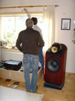
but will - if they sound as you said - find its way into my living-room, where it has to drive these ones:
These are "NON-DIY" speakers!
I can't await getting my BLameES - PCBs back from the "Etcher" and begin to solder.
Best regards - Rudi_Ratlos
your "Divine BlameES" will replace the "Standard DXAmp" that currently drives my tiny "Little Susis" (DIY - speakers), 20cm high, sitting on my writing desk,
An externally hosted image should be here but it was not working when we last tested it.
but will - if they sound as you said - find its way into my living-room, where it has to drive these ones:
An externally hosted image should be here but it was not working when we last tested it.
These are "NON-DIY" speakers!
I can't await getting my BLameES - PCBs back from the "Etcher" and begin to solder.
Best regards - Rudi_Ratlos
Yes, this is what i use in first place, then i use to assemble and go producing
modifications, 2 amplifiers, one standard, alike the simulator, and other tweaking and comparing..this way i use to improve sonics.
hard work man...this is the hard work, soldering iron burning our fingers.
Simulators i use all time long..we cannot survive without them.
regards,
Carlos
modifications, 2 amplifiers, one standard, alike the simulator, and other tweaking and comparing..this way i use to improve sonics.
hard work man...this is the hard work, soldering iron burning our fingers.
Simulators i use all time long..we cannot survive without them.
regards,
Carlos
Beautifull Rudi..thank you very much by these pictures posted.
Dx Blame ES has treble enougth to a half dead person...correct Wahab..that's it!
Listen here:
YouTube - A lot of treble, Divine Dx Blame ES.mpg
regards,
Carlos
Dx Blame ES has treble enougth to a half dead person...correct Wahab..that's it!
Listen here:
YouTube - A lot of treble, Divine Dx Blame ES.mpg
regards,
Carlos
keep on the improvements, your last version has fairly
good caracteristics..
it display good phase margin, even without output filter,so it
should be perfectly stable on capacitive loads..
distorsion is very low , with a balanced negative feedback ratio
at high frequency, about 32 db at 20 khz, robust enough to reduce
high frequency distorsion, and modest enough to make the thing
stable...
it just make me wonder, as you say that the treble is better than
in your older designs without vas buffer..
regards,
wahab..
ps : rudi s near field monitors are awsome.
Yes, this VAS is what is producing this result.
Also current sinks in the place of differential colector resistances as load.
I will soon use double circuit in the CCS...will have CCS and zener voltage regulator and a switch, the same way i made few weeks ago, comparing CCS with zener voltage regulator.
But the bass is not so good as the Dx amplifier...overall....it is the best i have made...but if you go to compare this one with the Dx amplifier, having an input filter, only bass..then the Dx amplifier will beat, and very easy.
This is "globaly" the best i have ever listened to, but, alike everything in this planet, is not absolutelly perfect (just close to the perfection), we have this high end with super quality against the low end that plays just fair.
Well, my bass speaker is not a sensitive unit, it is hard to move...i need high power to move this monster...maybe this is the main reason....but...the Dx amplifier, with the same output power, moves better this monster speaker.
Next model, to be made and released during march, release date 28 of March, will have some modifications (will try of course), new input impedance, smaller input capacitors, different currents, increased driver current, maybe CCS to drivers, new adjustment to bootstrapp action, other transistors, your suggestion (also Andrew T) 470uf or more FB condenser and some other details that i do not want to publish, or inform, as i do not want this one to be empty of candidates to assemble...if i start to talk too much, they will build nothing and will be waiting march
I hope you understand what uncle Charlie means about that, reason why i do not feed too much upgrades and update conversations because this is counter productive related my best wishes related to see hundreds of folks building this one.
I use to be educated and kind, but i do not want to make any modification in this one.
regards,
Carlos
Last edited:
@Wahab:
Are you really considering my "Little Susis"?
(Carlos: Only one post of mine to "destroy" your "Divine BlameES thread".)
...
PS : Rudi s near field monitors are awsome.
...
These "Near-field monitors" - called "Little Susis":
are the speakers (consisting of Dayton tweeter and Tangband broadband) a "new" AMP has to awake to life before it enters my living room.
Do you think my "Little Susis" are worth while opening a new "DIY-Speaker" thread, Wahab?
Best regards - Rudi_Ratlos
P.S. How did you guess they are sounding that beautifully?
Are you really considering my "Little Susis"?
(Carlos: Only one post of mine to "destroy" your "Divine BlameES thread".)
...
PS : Rudi s near field monitors are awsome.
...
These "Near-field monitors" - called "Little Susis":
An externally hosted image should be here but it was not working when we last tested it.
An externally hosted image should be here but it was not working when we last tested it.
are the speakers (consisting of Dayton tweeter and Tangband broadband) a "new" AMP has to awake to life before it enters my living room.
Do you think my "Little Susis" are worth while opening a new "DIY-Speaker" thread, Wahab?
Best regards - Rudi_Ratlos
P.S. How did you guess they are sounding that beautifully?
Last edited:
Very nice dear Rudi, but, i could not see fuses in these speaker panels
So, install fuses in your power amplifier output.
As you know, if your amplifier suffer a fault, a defect, a burn, and this is not impossible, you gonna have rail voltage in the ouput terminal.
Rail voltage going to the speaker means speaker dead...so, install a 5 to 6 ampere fuse in the output line, or in the speaker face panel.
regards,
Carlos
- Status
- This old topic is closed. If you want to reopen this topic, contact a moderator using the "Report Post" button.
- Home
- Amplifiers
- Solid State
- Dx Blame ES .... based into the Blameless, i am trying a new amplifier