Re: Hi!
Bah humbug. I like my electric water heater and damned if I'm going to change it.zeonrider said:@ ca90ss,it's 21st century.
It is not time for electric water heater elements, this is for last century
.
Regards zeoN_Rider
So Many Verbosity! For What?
Sorry for my input, but the initial question of the starter of this thread, i think it has answeered by far already. Each way which is available for making a dummy load has described. I ask from you, please, to don't make - as in many threads here - the thing a tiring debate of methods dear honorable members. According to my humble oppinion, each method described it is right by its side. Many methods are same between them and simply are realized under a diferent way. A dummy load it is a very simple (yet the use of a simple lamp of enough watts) case. The difficult thing, it is an implementation in practice. There is need of a lot of hand work simply.
Fotios
i have a Dale 8ohm/250W NI load that i use often as well as an 8ohm/500W load made with wirewound ceramics.
one load i have seen for burn-in purposes (don't try this at home kiddies) is a 0.1uf/250V mylar on a banana plug with the test signal being a 50khz sine wave set to a level producing half power out of the amplifier. this particular burn-in test was used at APT. the amp was very stable, so don't try this one unless you know your amp is stable. the capacitive load dissipates very little of the energy (the voltage and current are out of phase), all of the heat is dissipated by the amp. the burn-in test is run typically for 24hrs. the APT-1 had distortion /fault LEDs, so if any amp on a rack of 20 failed, the LEDs would turn from green to red.
for burn-in with resistor loads, maximum heat dissipation from a class B amp is at about 75% power. below that the transistors aren't sourcing as much current, above that the transistors average junction resistance gets lower (notice i said average).
i used to have a heathkit Cantenna that was a 50 ohm ldumy load for radio transmitters. it used oil as a coolant and was rated at 1KW with oil in it and about 200W empty. if you use water as a coolant, be sure to use distilled water! distilled water is nonconductive, any impurities (such as exist in tap water or spring water) will conduct, changing your load impedance and generating an explosive mixture of hydrogen and oxygen (!!!!!!!!!!!!!!!)

 a definite no-no......
one load i have seen for burn-in purposes (don't try this at home kiddies) is a 0.1uf/250V mylar on a banana plug with the test signal being a 50khz sine wave set to a level producing half power out of the amplifier. this particular burn-in test was used at APT. the amp was very stable, so don't try this one unless you know your amp is stable. the capacitive load dissipates very little of the energy (the voltage and current are out of phase), all of the heat is dissipated by the amp. the burn-in test is run typically for 24hrs. the APT-1 had distortion /fault LEDs, so if any amp on a rack of 20 failed, the LEDs would turn from green to red.
for burn-in with resistor loads, maximum heat dissipation from a class B amp is at about 75% power. below that the transistors aren't sourcing as much current, above that the transistors average junction resistance gets lower (notice i said average).
i used to have a heathkit Cantenna that was a 50 ohm ldumy load for radio transmitters. it used oil as a coolant and was rated at 1KW with oil in it and about 200W empty. if you use water as a coolant, be sure to use distilled water! distilled water is nonconductive, any impurities (such as exist in tap water or spring water) will conduct, changing your load impedance and generating an explosive mixture of hydrogen and oxygen (!!!!!!!!!!!!!!!)
a definite no-no......I repair many high powered PA amps and one of the final tests for the QSC amps i repair is a full power test into a dead short to set the current fold back circuit. these amps will produce full power into 2 ohms but will fold back the current to 5 or 6 amps when driven to a dead short. then test for recovery into a 2 ohm load.
So the test procedure is to connect a 2 ohm load and short the output at the same time. bring the amp up on a variac and watch for foldback. then remove the short and watch how the amp recovers into the 2 ohm load.
Some of these amps will do an easy 2000 watts into 2 ohms! I have determined that i need a much better power line to my shop and that i need a bigger test load.
I have a very large heatsink with 8x 4 ohm 100 watt Dale aluminum resistors mounted on it. I have it wired to provide dual 8 ohms at 200 watts, 4 ohms at 400 watts. and i could wire it for 8 ohms at 800 watts.
So far i have got the heatsink a little bit warm. not enough to even be considered hot. But i am concerned. I have done some "Full pulls" at 1000+ watts into 8 ohms with just 2 of those resistors rated for 200 watts. The "pulls" are short in duration. not more then a few seconds each but i am so far over the rated power for the resistors that i fear damaging them.
I wish i had purchased at least a second one of these heatsink assemblies.
After reading about heating elements in buckets of water. I wonder if i shouldn't build a larger load? Something rated for at least 2kw
Zc
Hi ZC!
Like you I,repared many2 Pow.Amps.
My dummy load have 32pcs. Dale 50W/3,9 Ohm,that is :
4 x 400W/8 Ohm
2 x 800W/4 Ohm(w.bridges)
1 x 1600W/2 ohm(w.Bridges)
I fired up one of my Crests one ch( 2 Ohm ) full power, about one hour without damage!
Only thing is heat2.
Once again it is 21st century!
Regards zeoN_Rider
another possibility is an active load using MOSFETs. you can (and some built-in protection circuits in speakers use this method) feed a set of MOSFETs with a bridge rectifier, and use an adjustable DC bias on the gates to vary the load resistance. it's nonlinear in the crossover region because of the bridge rectifier, but for burn-in testing of an amp where you want to run the amp at max dissipation it should work just fine. it would also save bench space since resistors for the same dissipation are much larger than transistors and a heat sink. NASA uses active loads like this for load testing AC power inverters.
According to
http://www.allaboutcircuits.com/vol_1/chpt_12/6.html
We have:
Iron ---------- Element --------------- 0.005671
Tungsten ------ Element --------------- 0.004403
Aluminum ------ Element --------------- 0.004308
Copper -------- Element --------------- 0.004041
.........
Nichrome ------- Alloy ---------------- 0.00017
.........
Constantan ----- Alloy --------------- -0.000074
measured in "alpha" per degrees Celsius
Nichrome is about 1/20 that of cooper. Good enough for speaker simulation. Off course Constantan is better. ("Constant...")
I measured the "cold" resistance or various heater elements, and it is always very close to the theoretical value derived from power/voltage.
unclejed613 said:just curious.... does it's resistance change much as it heats up? nichrome has a large positive tempco (though not as large as tungsten), and that's what most heating elements are made of.
Hi unclejed613
From my old book, when i was student (and "when i was young" as says an old song of Supertramp) Tecnology of Electronic Parts i taken the following data:
1) Nichrome thermal coefficient (a) = 0,00025
2) Rt2 = Rt1 X [ 1 + a X (t2 - t1)] where:
t1 = ambient temperature
t2 = heating temperature
Rt1 = resistance of NiCr at t1 i.e. t1=20degC
Rt2 = resistance of NiCr heated at t2
Suppose that a NiCr resistor has a nominal value of 8Ù at 20degC i.e. R20. What is its resistance when its body temperature increased at 100degC i.e. R100?
Solution: R100 = R20 X [ 1 + a X (100 - 20)] =
= 8Ù X [ 1 + (0,00025 X 80)] = 8Ù × 1,02
and thus, R100 = 8,16Ù
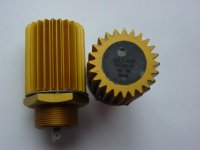
As we can see, the variation it is very slight but we must take into account that a free in the air NiCr heating element increase very fast its temperature (it is its work moreover) at 250 to 300 degC when operate. For our work, we must prohibit a such increasing by the use of large heatsinks, fan coolers etc. A such thing it is the dummy load presented in the photo of my post.
The materials that used are: 1) Two pieces of edgewound NiCr 0,2 X 2 mm each one 1,5m length 2) Three pieces of mica-papper (i don't know its name in English, in Greece the craftsmen call it "micalites") but it is the most common isolating material found in all heaters 3) Two pieces of chip heatsink each one of 0,5m length. The NiCr edgewound wires twisted each one 2 times around a mica-paper card board, giving thus two 8Ù loads, and then pressed between the two heatsinks very tightly isolated from these with two another mica-paper card boards. I have checked many times some Peavey CS1200 after repairing in half power for one hour with sweep signal 100-10000Hz and the surface temp of the d. load never exceed the 60degC. One interesting property of a such made d. load it is that it is by 99,99% clear resistive. You can suppose this from the photo and from my description. To make this d. load it needs much of craftsmanship but i believe this is not a problem for a skilled craftsman such you.
Fotios
Hmm..
first, typical high power wirewounds (like Arcol HS for example) really have negligible inductance in the audiorange.
Second.. why would anyone working with amps wanna know how the circuit performs into a resistive load but not in a real life reactive load??
Resistive dummy load may be a good starting point but you WANT inductance and capacitance in the dummy load to check how the amp perform into real life load. You may wanna have a couple of dummys at your hand that are representative of different speakers.
/Peter
Pan said:Hmm..
first, typical high power wirewounds (like Arcol HS for example) really have negligible inductance in the audiorange.
Second.. why would anyone working with amps wanna know how the circuit performs into a resistive load but not in a real life reactive load??
Resistive dummy load may be a good starting point but you WANT inductance and capacitance in the dummy load to check how the amp perform into real life load. You may wanna have a couple of dummys at your hand that are representative of different speakers.
/Peter
Simply you can put a 2ìF MKT cap in parallel with the resistive d. load to simulate the worst case of an electrostatic speaker. For the inductance as i know there is no need to take into account. It is killed moreover from the zobel network. To being in place to observe the behavior of the output in inductive loading, you must first remove the zobel from the output. Also maybe you will cry afterwards this for the destroyed output transistors.
Fotios
when doing distortion measurements, you want to have a resistive load. a reactive load changes it's impedance with frequency, and so the harmonic content seen into a reactive load is different than a resistive load. as an example, let's say a load has a parallel resonance at 2khz. when doing a distortion measurement at 1khz, any 2khz components in the output will be developed across a higher impedance than any other frequency, and so will be exaggerated. similarly, if it were a series resonance, the 2khz component would be feeding a very low impedance compared to the nominal load impedance, and would be attenuated. yes i would have a "real world" load for testing (stability, clipping behavior, etc...), but i also need a resistive load for accurate distortion and noise measurements.
Well my point being use both. What god is it if the amp perform well in a resistor but collapses when hooked up to a speaker with its rollercoaster impedance curve.
Giving the amp a hard job and letting it sweat is the whole idea.. off course the distortion increases but that's the point. The most interesting performance of an amp is IMO that you'll see when hooked up to a speaker.. If the amp sound good then (free from audible colorations) then obviously it is ok.
fotios;
yes but you'd also want big coils and caps in order to emulate (?) the fundamental resonance of boxed (or free air for that matter) speakers and also crossovers.
/Peter
unclejed613 said:but i also need a resistive load for accurate distortion and noise measurements.
Is this just for the sake of standardisation, or are there other reasons?
@ Pan, unclejed613, fotios:
I agree with you all (about last posts)
We are telling almost the same story....
Small annotation:
Many amplifiers (especially non-commercial, minimalist, "purist".... amps) don't have a zobel network, so output impedance is highly variable, depending on speakers/xo/(cables) frequency-related curves.
I agree with you all (about last posts)
We are telling almost the same story....
fotios said:
For the inductance as i know there is no need to take into account. It is killed moreover from the zobel network. To being in place to observe the behavior of the output in inductive loading, you must first remove the zobel from the output. Also maybe you will cry afterwards this for the destroyed output transistors.
Fotios
Small annotation:
Many amplifiers (especially non-commercial, minimalist, "purist".... amps) don't have a zobel network, so output impedance is highly variable, depending on speakers/xo/(cables) frequency-related curves.
Peter, also me i respect your point of view. The difference between our points of view there is in that: i am speaking as a proffesional, because my job it is the audio electronics. So, for estimating the behaviour of an amplifier i remove first all the output filters such as inductor, zobel etc. before the test with the resistive d. load. After this, and for making real world tests i place again the filters in the output and i make the test with the 2ìF cap connected also in output, for estimating with the scope the ammount of ringing caused in a square wave injected in the input. If the ringing it is unacceptable, then i increase the value of output inductor by adding more turns of wire. As for the inductive loading, simply i push hard in 20KHz and above the amplifier and if the zobel resistor heated dangerously, then i place more resistors in series/parallel to obtain the same ohmic value but increasing the power value. To be sure, from the begining i place a 10Ù/10W resistor in the common used zobel scheme. I have seen also in some P.A. amplifiers such Peavey or Crest instead the usual 10Ù resistor, a 5,6Ù resistor of 10W in series with the usual 100nF cap, and some times a resistor of 20W!
After this, no one it is in place to estimate the behaviour of output filtering when connected in the thousands different loudspeakers of the market. Of course, if you have a concrete pair of loudspeakers and you want to make any improvement in your custom made amplifier to drive these as much better, you can make your experiments for these exactly loudspeakers. But me and as i suppose unclejed which are proffesional lab owners to earn "our daily bread" (as we say in Greece) what can we do in the practice? The hobby it is another history. So, any project when connected in the real load to make its job which is to amplify music information and to drive an unknown load, in practice it is a such case as the black holes, the big bang, etc.
As said the Ephesian ancient philosopher Heracletus before 2300 years, "Everything in the world it is under flow". And the Syracusian ancient engineer/philosopher Archimedes: "Give me a place to stand on, and I will move the Earth."
Friendly
Fotios
- Status
- This old topic is closed. If you want to reopen this topic, contact a moderator using the "Report Post" button.
- Home
- Amplifiers
- Solid State
- dummy load