Decided to return the KT88's. I realize I am pushing the transformer, and I don't need that much power. I ordered a quad of 6V6-S's. Looks like they are good up to 500V.
JJ 6V6S
I also have some EL84's, so I'll try out both. I am a little concerned about the choke 200ma rating when used with the EL84s. I probably should have ordered a bigger choke, but I am out of real estate on my chassis.
JJ 6V6S
I also have some EL84's, so I'll try out both. I am a little concerned about the choke 200ma rating when used with the EL84s. I probably should have ordered a bigger choke, but I am out of real estate on my chassis.
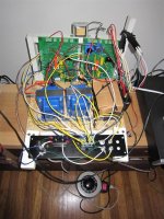
It Works!!
I hooked it all up a on temporary piece of plywood, just to work out all the details, take measurements etc. A friend with a mill is cutting some holes in a proper chassis for me meanwhile.
Anyway, it sounds AWESOME. Absolutely fantastic. Thanks George for a killer design of the SE, and it really works great in PP.
I was a little concerned that the OPT were a little too big for the power I would be running them at, but there is a lot about of detail coming through. And the bass really extends very deep and clear.
In fact, the EL34's are probably way more power than I need. But I will run them for a while to see how I like them. I'll pop in the 6V6-S's later.
I feel like I am in the minority here, but after listening for a few hours, I tend to prefer the sound of UL vs triode strapped. In triode, I find the treble kind of grating and irritating, and the bass does not extend down so far. It could be that my speakers which are horn loaded, so I don't need need the mids highlighted.
Anway, I am very pleased. Thanks again George.
Attachments
Tube Selection
Thanks for the complements, but it turned out to be a lot easier than I thought at the outset. Mostly followed George's instructions, and learned a few things along the way.
One thing I learned is that although the El34's do sound good indeed, it is a whole lot of power. Although the amp can be very delicate at low levels, it can be downright pummeling. Also, since I am using a single GZ34 tube + C354 choke, I seem to have restricted myself to 200ma MAX. The choke is getting damn hot and I've heard that the GZ34 doesn't like much more than 200mA either. I currently have the 84's biased at ~53ma/23W.
I am going to try to select some not so pummeling tubes (to my ears and power supply).
I'm looking for some tubes that like the 420-450 range, and that bias in this situation in the less than 40mA range.
So far, some likely candidates are:
6V6-S
7591-A (I think)
Any other recommendations? New production only, and not impossible to find.- Thanks
Also, since I am using a single GZ34 tube + C354 choke, I seem to have restricted myself to 200ma MAX. The choke is getting damn hot and I've heard that the GZ34 doesn't like much more than 200mA either.
You can use 2 5AR4's and 2 chokes if you want. Just wire the power transformer secondary to both boards, and then run each board off of its own rectifier and choke. That's how I had mine connected. Your transformer has a 4 amp 5 volt winding, so there is enough current to feed 2 rectifiers. The rectifiers are essentially in parallel since they share a common heater winding.
Any other recommendations? New production only, and not impossible to find.-
Most 6L6GC's should work. I use the cheap Chinese ones. You are still going to get loud, about 30 WPC worth of loud. I think that you will find that the EL34's sound better though.
You can use 2 5AR4's and 2 chokes if you want. Just wire the power transformer secondary to both boards, and then run each board off of its own rectifier and choke. That's how I had mine connected. Your transformer has a 4 amp 5 volt winding, so there is enough current to feed 2 rectifiers. The rectifiers are essentially in parallel since they share a common heater winding.
Ok, so all you are saying is populate both power supply sections of both boards. Have the HV secondary as well as the 5V secondary connect to both boards. Connect the 2 chokes to their corresponding board and thats it.
Since the rectifier filament appears to be tied to the unfiltered B+, and if each rectifier tube's output is slightly off with to respect to the other, I would think that the higher unfiltered B+ would 'go into' the lower potential B+. I have paralleled 2 power supplies before (not tube rectified), in which case I would put a diode on the output of each one, and connect the cathodes together. But really, I don't quite understand how the heater winding works, especially in a tube rectifier, so I totally take your word for it. I just want to make sure my interpretation of what your saying is correct before I go making 400+V connections.
I would put a diode on the output of each one, and connect the cathodes together.
Think about it this way. The HV primaries are going to both boards, so the plates of the rectifier tubes are wired together. The 5 volt heater windings are going to both boards so the cathodes of the rectifier tubes are wired together. So what you have are two rectifier tubes wired directly in parallel. Yes they will not share the current exactly equally, but two tubes in parallel will deliver more current than one alone. It would be wise to use identical rectifier tubes to help equalize the current sharing. If you haven't placed C1 on one of the boards leave it out. This will make life easier on the tubes on start up and won't affect the voltage much. You need ONE C1 but two may be too much for the weaker of the two tubes.
You could simply wire the two chokes in parallel and run both boards on the doubled up power supply, but there is some channel seperation improvements to be gained by seperating the two channels after the rectifiers. So one choke drives each board using the C2 on its particular board. The ckokes will run cooler since each only runs one channel. This provides most of the benefit of dual mono operation without the expense of two power transformers.
Make sure each transformer wire goes to the same terminal on each board.
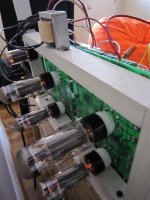
So I did what you said. Jumped the HV secondary and the 5V secondary from board 1 to board 2. I was careful to keep the same polarity on each. On board 2 I left off C1. I have 2 chokes now- each wired to its corresponding place on each board. The chokes are not 100% identical. One I got at dynakit parts, and is unshielded and as usual fairly ugly. The other is the same spec, but I bought from Triode. Triode has the nicer looking shielded version, and since I am out of room under the chassis, I figured this one looks OK to put on top.
Anyway, it was odd that the choke on board 2 (Triode elec) was getting warm (but not hot), and the choke on board 1 was not (dynakitparts).
I measured B+ on both boards. B+ on board 1 was 422V and on board 2 it was 407V.
Upon closer inspection, I realized that the new rectifier tube, on board 2, was not the same as the first one. My original rectifier on board 1 was a sovtek 5AR4. I ordered the same part again, but for some reason they sent me a JJ GZ34. Anyway, maybe this explains the weirdness. I'll see if I can return this JJ for the actual part I ordered.
Could the use of 2 different tubes cause this much of a discrepancy? I also wonder why one choke was so much warmer than the other. I'll check my connections again, but I am pretty sure its all correct. I have R2 installed on both boards. Is this correct?
I just realized that I had both red wires from the middle of the OPT's connected together, both tying to the 2nd board's B+. That is now corrected, and each red wire from each OPT goes to its corresponding B+ on the different boards.
Each board is getting about 415-420 V now. I still plan on returning the JJ for a Sovtek.
When I had one rectifier and one choke feeding both boards, B+ was around 425-430V.
Each board is getting about 415-420 V now. I still plan on returning the JJ for a Sovtek.
When I had one rectifier and one choke feeding both boards, B+ was around 425-430V.
Last edited:
High Frequency Extension in Triode vs UL
I've been switching a lot back and forth between UL and triode. On one hand, I feel that triode has a much more even presentation. And as many people have noted, UL can be much punchier, with lower lows and higher highs. In many ways, I miss that high frequency sparkle when listening in triode, but prefer triode for other reasons.
My question is very specific regarding the high frequency part.
Is the HF rolloff due to the miller effect of the output tube? So in this case, perhaps a tube with the lowest possible Cg1 will give me the best high frequency detail?
Or, is it that much of the HF detail is lost in the transformer, and is not 'making it through'? I am using the 25W Edcors, which maybe are a little large?
I suspect it is a combination of both, or perhaps some other factors I am not aware of.
I cannot answer your question but have observed similar, regarding PP amps. I have a Simple PP and a 6P1P PP amp and found that triode mode seemed to have less HF and less "sparkle" overall. I would be interested to hear an answer to your question too...
Just some food for thought. I don't have a very technical background but have done a bit of experimenting and listening the last couple of years. I believe you don't have any GFB (global feedback) in your amp due to the balanced input drive system. Generally I have found best results using pentode mode without GFB. With no GFB, the amp needs to run as clean as possible, which requires some experimentation. Some tweaks that have worked very well for me: (in no particular order)
1. Varying the size of the screen grid resistors for best sound.
2. Varying the screen grid voltage by using a regulator. Some amps benefit from a reg, some don't.
3. Mosfet source followers to drive the output tubes (ZVN0545 as per Baby Huey schem or the Tubelab SE method)
4. Use of LED's as cathode loads for the output tubes.
5. I have found that it seems the bigger the tube, the harder they are to "tame". You might get a nice surprise with those 6V6's you ordered.
What I like about this hobby is that a person can tune the amp to suit their own ears, system, speakers, room. All good clean fun...")
Just some food for thought. I don't have a very technical background but have done a bit of experimenting and listening the last couple of years. I believe you don't have any GFB (global feedback) in your amp due to the balanced input drive system. Generally I have found best results using pentode mode without GFB. With no GFB, the amp needs to run as clean as possible, which requires some experimentation. Some tweaks that have worked very well for me: (in no particular order)
1. Varying the size of the screen grid resistors for best sound.
2. Varying the screen grid voltage by using a regulator. Some amps benefit from a reg, some don't.
3. Mosfet source followers to drive the output tubes (ZVN0545 as per Baby Huey schem or the Tubelab SE method)
4. Use of LED's as cathode loads for the output tubes.
5. I have found that it seems the bigger the tube, the harder they are to "tame". You might get a nice surprise with those 6V6's you ordered.
What I like about this hobby is that a person can tune the amp to suit their own ears, system, speakers, room. All good clean fun...
There are several things at work here. Some make for a measurable difference in frequency response, and there are some psychoacoustics at work here too. Generalizations don't hold up well.
Miller is working overtime in triode mode, and has the day off in pentode mode. This can reduce the HF response. On the other hand, the tube has the lowest dynamic resistance in triode mode. This can tame a marginal OPT. These affect the frequency response in opposite directions with the absolute result depending on the characteristics of the tube and the OPT.
The characteristics of the amp itself will change with the mode. In triode mode the output impedance and the distortion and gain are the lowest. This usually results in the cleanest and most accurate sound. In many cases triode mode can be clean enough to run without any feedback at all.
Pentode mode is just the opposite with a high output impedance more distortion and gain. UL is somewhere in between. Very few pentode amps can function without any feedback. The feedback will lower the distortion and output impedance back towards the triode levels, with some exceptions. The obvious is the increase in output power, but the trade off is an increased level of higher order harmonics. Often the increased harmonic content is the source of the high end sparkle that some users report. Take this too far, and you get "pentode nastiness". Apply too much feedback, and your pentode amp starts to sound like a solid state amp.
These effects are very much dependent on the individual amp, and of course the speakers. Some speakers require a low output impedance to control the woofer cone movement. This means triodes or feedback, sometimes even both.
There is one big difference between an SE amp and a P-P amp. The P-P amp inherently cancel much of the second harmonics generated in the output stage. This means that the distortion produced with a small amount of feedback will be mostly third harmonic. Third harmonic distortion in reasonable amounts doesn't sound bad and adds high end sparkle. It also makes the bass sound fuller. Apply more feedback and the 5th and 7th start to appear and things get nasty.
The SE amp has a lot of second harmonic. In triode mode without feedback, the second harmonic will be dominant, often as much as 5%. This provides the "euphony" that hooks the SE amp user. A SE pentode amp with feedback may have a lower overall distortion level, but the makeup may no longer be predominantly second harmonic. Here the trade off takes a bit more tweaking to get right, and the type of speaker is more important. UL again falls in between.
I have a Simple SE with a switch for triode or UL. It has another switch to engage about 5 db of local cathode feedback on the output stage. I can also use several different output tubes. I have found that the optimum settings depend on the speakers and the type of music being played. Big inefficient speakers and dynamic music demand KT88's in UL mode with cathode feedback. More mellow music works in triode mode without feedback, but the KT88's still sound best. Take the same amp to some efficient full range speakers and it sounds absolutely gross in UL mode. Triode with EL34's are the ticket here, on all music.
Thanks for the response. I am learning a lot with this project. There certainly are a lot of balancing factors at work as I am learning with my ears.
BTW- I popped in the 6V6's, biased at about 11W idle current. These are sounding the best to me so far. The amp is running a hell of a lot cooler, which is a major plus as well.
BTW- I popped in the 6V6's, biased at about 11W idle current. These are sounding the best to me so far. The amp is running a hell of a lot cooler, which is a major plus as well.
Amp Finished
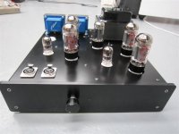
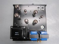
I thought this would be a fitting post to wrap up this thread.
I finally put this amp in a chassis, so here are a few pics. Also, I did a writeup on it, with some wiring diagrams, so please check it out.
Click here for the link, and go to the electronics tab and click on 6v6 amp. I hope the web page will help whoever may decide to take a similar route.
All in all, it was fun project, and thanks for the help along the way.
Attachments
- Status
- This old topic is closed. If you want to reopen this topic, contact a moderator using the "Report Post" button.
- Home
- More Vendors...
- Tubelab
- Dual Simple SE's in Push Pull w Differential Input