As long as Junm leaves the mains side alone, there is only a material risk: diodes melted or transistors destroyed.
He is talking about 0 - 220V: this is more of concern, since I don't see what it has to do with the topic.
The secondary has to be kept separate from the primary, and the type of mains system should have nothing to do with it.
Anyway, the last schematic will not work, and even if the problem is corrected, there are good chances the amplifier (and loudspeakers) connected to it will blow.
When i plug it i'm waiting for a smoke , meltdown or fuse blow but i don't see it that's why i proceeded without any idea of the risk..... Yes the mains are isolated...maybe this prolonged the agony. Good that I brought out here, i'm really planning to open another thread to ask idea if it will work...but i'm hesitant coz some pals dont give pointers how to do it correctly but instantly mock u as i seen on other threads. sorry pals no offense...
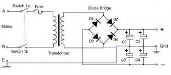
The circuit looks perfectly safe to me. D1 and D2 provide half-wave rectification for the negative and positive rails respectively.
D3 and D4 are permanently reverse biased so they don't do anything useful, but they don't do any harm either, or cause any danger.
If you leave out D3 and D4, it's just an ordinary voltage doubler.
")
D3 and D4 are permanently reverse biased so they don't do anything useful, but they don't do any harm either, or cause any danger.
If you leave out D3 and D4, it's just an ordinary voltage doubler.
Attachments
The circuit looks perfectly safe to me. D1 and D2 provide half-wave rectification for the negative and positive rails respectively.
D3 and D4 are permanently reverse biased so they don't do anything useful, but they don't do any harm either, or cause any danger.
If you leave out D3 and D4, it's just an ordinary voltage doubler.
That's what i see too....
If you leave out D3 and D4, it's just an ordinary voltage doubler.
That's right, I had seen the shorted diode and didn't go further.
Pavlovian reaction I suppose
If you leave out D3 and D4, it's just an ordinary voltage doubler.
yes, this is the right thing to do.....it is still a full wave rectifer, transformer utilization os good at some sacrifice in regulation...
I didn't notice the extra ground connection, as it didn't occur to me that someone would include diodes which don't do anything. The extra connection turns a full-wave bridge rectified supply (with capacitive 'centre tap' - not a good idea) into two half-wave rectified supplies (with two spare diodes). Note that the total output voltage will have doubled, and the maximum output current more than halved. Still a poor supply, but not as bad as the one which started this thread.
a doubler using just 2 diodes is actually on my mind but i don't have any 5 Ampere that time but i have lots of bridge rectifier so tried it. I can't rewind my trafo since the lamination was welded and hard to dismantle. so i tried it this way. But i don't encourage anybody here to do this.
anyway thanks guys for your replies.
anyway thanks guys for your replies.
The circuit looks perfectly safe to me. D1 and D2 provide half-wave rectification for the negative and positive rails respectively.
D3 and D4 are permanently reverse biased so they don't do anything useful, but they don't do any harm either, or cause any danger.
If you leave out D3 and D4, it's just an ordinary voltage doubler.
Hello,
Electronics and electrical power is a second language to me. I started speaking mechanical things like fans and pumps. Then the controls and power that are required to make the fan and pump motors function crept into the picture. Sometimes you need to leave the plantation where you feel safe to gain the benefit of the bigger view.
Yes without D3 and D4 the circuit would function as a half-wave voltage doubler.
No D3 and D4 are not always reverse biased, with them included in the circuit the circuit functions as a full-wave voltage doubler. Going back to the motor example you can ground 3 phase transformers or motors as “Y” or delta you can ground the center of the “Y” any of the 3 phases or center tap between any of the phases. For our power supply we could choose to ground the positive end, the negative end or the center point between the phases as shown in this a split rail power supply.
Yes both rails should have a bleed resistor to the grounded neutral conductor.
Voltage doubler - Wikipedia, the free encyclopedia
DT
All just for fun!
Last edited:
Yes, D3 and D4 are always reverse biased. They are directly connected across the DC output of the supply. Their reverse bias can be reduced to zero by applying a short to the output, but then the supply is not very useful.DualTriode said:No D3 and D4 are not always reverse biased
New Idea???

I saw that but i need a secondary +/- power supply would this work? (LINK)
Hi,
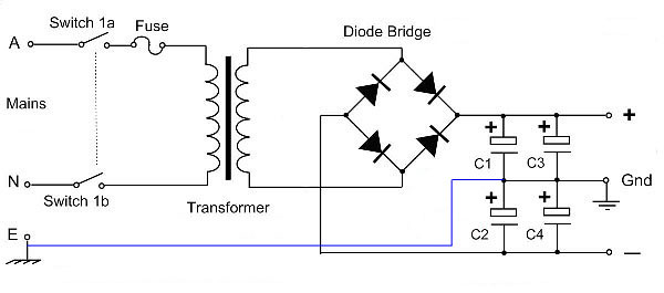
I was wondering, what would be the possible problems with this design?
My transformer only has a single secondary winding of 42V. I'm intending to connect it to a filter board, that has AC-GND-AC on the input side. I tested it without connecting the filterboard GND to EARTH (blue line), it gave a split voltage of +/-30V on the filterboard output.
It should power two LM3886 amplifier boards as the end result.
I saw that but i need a secondary +/- power supply would this work? (LINK)
No, unless you can guarantee that under all conditions (including faults) the circuit draws exactly the same current from + and - rails. Even then you would need equalisation resistors across the caps.
Would this work then? I need two +/- supplys and dont want to tap onto the other one.
Attachments
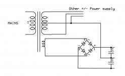
No, it won't work. For a simple centre-tapped supply you either need a centre-tapped secondary feeding a bridge, or use two half-wave supplies of opposite polarity sharing a secondary. If for some reason you don't want to do this, then you have to simulate a centre-tap by using active circuitry fed from a single supply.
Here is a possible solution.
It is rather far-fetched, more like noodle-twisting on a grand scale than a really practical proposition, but it works anyway (and I think it's original).
The middle potential is created by a capacitive divider (that uses no active power) DC-restored to the supply rails.
The result is identical to that of a resisitive divider, but without the wasted calories.
The virtual ground thus created has a certain internal resistance that depends on the size of the divider's capacitors.
In this example, they are 22µ, which is still of manageable size for 63V mylars.
Larger values could be used if large unbalance currents are expected, and if the transformer can tolerate the supplementary current caused by the reactive load.
Attachments
Last edited:


In principle, for ever: they are subjected to ~110mA of rms current in this example, and Wima's MKS4 can tolerate up to 250Hz at their full 40VAC voltage rating.Clever idea. Too clever? How long will the 22uF last, as both are pumping current?
http://www.wima.de/EN/WIMA_MKS_4.pdf
Other manufacturers must have very similars specs for this kind of product.
Attachments
One thing that might be a problem with that circuit is that with low load current, the output voltages can rise up to double the normal value.Here is a possible solution...
- Status
- This old topic is closed. If you want to reopen this topic, contact a moderator using the "Report Post" button.
- Home
- Amplifiers
- Power Supplies
- Dual polarity power supply with a single secondary transformer?