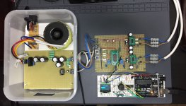
As a lockdown project I'm building a mini amp based around two PAM8320 mono class D amps and a TDA7439 three-band digitally controlled preamp/input mux/processor, and I thought I'd share it here. I'm a relative newbie to electronics (also working on a 74-series logic version of the 6502 microprocessor) but have really been bitten by the DIY amp bug.
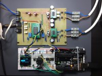
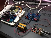
It's currently in prototype, mainly built on stripboard, and an Arduino (clone) used for the front-end and I2C interface for the TDA7439. I programmed all the code for the Arduino myself.
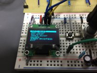
Sound wise, I'm quite impressed. I don't think it will set anyone's world on fire, but these little devices are inexpensive and don't require many supporting components. The TDA7439 is working beautifully with the rotary encoder/OLED front-end, and was a doddle to get working with the i2c interface. The PAMs are supposedly able to deliver 20W into 4 ohms. They've been driving my old (circa 1998) Monitor Audio Monitor 2 bookshelf speakers, which I think are 8 ohms, drawing just over 1 amp when going loud enough for my wife to bear!
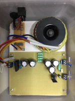
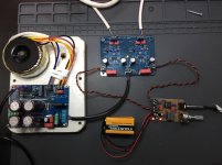
Since I wanted to embrace the whole DIY thing, rather than use a SMPS to power it I decided instead to go with an unregulated supply. Given that the PAMs have an ideal input voltage of 12v I went with a 9v transformer, that when rectified and smoothed gives me around 13v. The smoothing caps are cheapy "Multicomp" ones but from a reputable source (Farnell in the UK) - 5x3,300uF at the moment. I measured about 25mA of ripple with my scope. There's a bit of a hum, that was quite bad originally but I've tamed it quite a lot by redoing ground lines and moving some components. TBH it's not bad considering the horror-show on the back of the amp board (I daren't show it for fear of being asked to leave and never return ). When I build it properly I think I'll be going with Nichicon UPW series 6,800uF 25v x4, which should halve the ripple, and having much better grounding will tame the noise even further.
You'll see from the attached images that the two amps are using different capacitor types for input and bootstrapping - I'm not hearing any difference to be honest but was just trying out ceramics and film caps. Any thoughts on what to use/avoid? I read that ceramics should generally be avoided over certain values but all of the modules I've seen tend to use them in abundance.
Anyway, I think I'm just about done with the prototype, so will move onto building the PS & amp onto a single PCB. The front-end will probably be stripboard and an Arduino Nano for version 1 of the build proper. I've attached the schematic for the PS and amp. I imagine the CRC filter and the RC filter at the end of the PS could do with some thought regarding values, as I kind of borrowed the values from existing schematics, having not much clue about such things
Christian
It's currently in prototype, mainly built on stripboard, and an Arduino (clone) used for the front-end and I2C interface for the TDA7439. I programmed all the code for the Arduino myself.
Sound wise, I'm quite impressed. I don't think it will set anyone's world on fire, but these little devices are inexpensive and don't require many supporting components. The TDA7439 is working beautifully with the rotary encoder/OLED front-end, and was a doddle to get working with the i2c interface. The PAMs are supposedly able to deliver 20W into 4 ohms. They've been driving my old (circa 1998) Monitor Audio Monitor 2 bookshelf speakers, which I think are 8 ohms, drawing just over 1 amp when going loud enough for my wife to bear!
Since I wanted to embrace the whole DIY thing, rather than use a SMPS to power it I decided instead to go with an unregulated supply. Given that the PAMs have an ideal input voltage of 12v I went with a 9v transformer, that when rectified and smoothed gives me around 13v. The smoothing caps are cheapy "Multicomp" ones but from a reputable source (Farnell in the UK) - 5x3,300uF at the moment. I measured about 25mA of ripple with my scope. There's a bit of a hum, that was quite bad originally but I've tamed it quite a lot by redoing ground lines and moving some components. TBH it's not bad considering the horror-show on the back of the amp board (I daren't show it for fear of being asked to leave and never return
). When I build it properly I think I'll be going with Nichicon UPW series 6,800uF 25v x4, which should halve the ripple, and having much better grounding will tame the noise even further.You'll see from the attached images that the two amps are using different capacitor types for input and bootstrapping - I'm not hearing any difference to be honest but was just trying out ceramics and film caps. Any thoughts on what to use/avoid? I read that ceramics should generally be avoided over certain values but all of the modules I've seen tend to use them in abundance.
Anyway, I think I'm just about done with the prototype, so will move onto building the PS & amp onto a single PCB. The front-end will probably be stripboard and an Arduino Nano for version 1 of the build proper. I've attached the schematic for the PS and amp. I imagine the CRC filter and the RC filter at the end of the PS could do with some thought regarding values, as I kind of borrowed the values from existing schematics, having not much clue about such things
Christian
Attachments
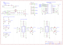
There were a couple of "gotchas" that had me stumped for a while - the H-bridge power supply lines into each amp are described in the datasheet as "Power supply for negative H-bridge, not connected to PVCCP or AVCC". That had me wondering if I needed 3 completely separate 12v lines per amp, which would've been unrealistic. However there was thankfully an evaluation board user guide for this chip that described how to achieve this. It turns out that PVCCN and PVCCP can be the same supply and you just need to "decouple" (not sure if that's the right word) AVCC using a 10ohm resistor and some caps to ground. After that the amps worked pretty well.nigelwright7557 said:class d on stripboard ?
you did well to get that working.
Admittedly stripboard is far from the ideal way to build such an amp. I've reworked it quite a few times so the backside now looks like a twisted solder nightmare - it's a wonder it works at all, let alone as well as it does
Which amps were you working with? I went for these as they're relatively simple devices to get started with. I think the bigger TI chips that are commonly discussed on here would present considerable challenges to prototype like this.i have struggled getting them working on carefully laid out pcb's.
Thanks.
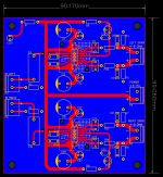
I've decided to split the project into three separate boards (power supply, preamp/processor and power amp). Here's my first pass at the power amp board. Would love feedback. I'm pretty happy with the layout - a pretty much unbroken ground plane, nice and symmetrical, etc.
Some capacitor questions:
- Do you think the board needs some power input caps, or will the IC decoupling caps do?
- When it comes to the IC decoupling caps, are the Nichicon audio-class caps worth going for, e.g. the UKW, or UKZ (Muse), or is it better to go with low impedance types like the UPW series? There are two 1000uF (C1, C13, C16 & C28), and two 10uF caps (C2, C12, C17 amd C27) per amp IC. Where exactly are these "audio-class" caps designed to go in the circuit?
- Any recommendations from personal experience regarding capacitor choice?
Thanks!
Attachments
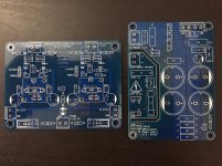
Finally got the amp and power supply boards finalised and fab'd. They turned out nice (although the cutout on the PS board separating the primary and secondary sides is a weak point!). The preamp is a simple LM4562 based board powered by a couple of 9v batteries. Sounds great, and goes loud without breaking a sweat (still driving the Monitor Audio Monitor 2 bookshelf speakers).
Attachments
As a lockdown project I'm building a mini amp based around two PAM8320 mono class D amps and a TDA7439 three-band digitally controlled preamp/input mux/processor, and I thought I'd share it here. I'm a relative newbie to electronics (also working on a 74-series logic version of the 6502 microprocessor) but have really been bitten by the DIY amp bug.
It's currently in prototype, mainly built on stripboard, and an Arduino (clone) used for the front-end and I2C interface for the TDA7439. I programmed all the code for the Arduino myself.
Sound wise, I'm quite impressed. I don't think it will set anyone's world on fire, but these little devices are inexpensive and don't require many supporting components. The TDA7439 is working beautifully with the rotary encoder/OLED front-end, and was a doddle to get working with the i2c interface. The PAMs are supposedly able to deliver 20W into 4 ohms. They've been driving my old (circa 1998) Monitor Audio Monitor 2 bookshelf speakers, which I think are 8 ohms, drawing just over 1 amp when going loud enough for my wife to bear!
Since I wanted to embrace the whole DIY thing, rather than use a SMPS to power it I decided instead to go with an unregulated supply. Given that the PAMs have an ideal input voltage of 12v I went with a 9v transformer, that when rectified and smoothed gives me around 13v. The smoothing caps are cheapy "Multicomp" ones but from a reputable source (Farnell in the UK) - 5x3,300uF at the moment. I measured about 25mA of ripple with my scope. There's a bit of a hum, that was quite bad originally but I've tamed it quite a lot by redoing ground lines and moving some components. TBH it's not bad considering the horror-show on the back of the amp board (I daren't show it for fear of being asked to leave and never return
You'll see from the attached images that the two amps are using different capacitor types for input and bootstrapping - I'm not hearing any difference to be honest but was just trying out ceramics and film caps. Any thoughts on what to use/avoid? I read that ceramics should generally be avoided over certain values but all of the modules I've seen tend to use them in abundance.
Anyway, I think I'm just about done with the prototype, so will move onto building the PS & amp onto a single PCB. The front-end will probably be stripboard and an Arduino Nano for version 1 of the build proper. I've attached the schematic for the PS and amp. I imagine the CRC filter and the RC filter at the end of the PS could do with some thought regarding values, as I kind of borrowed the values from existing schematics, having not much clue about such things
Christian
Hi,
Can you provide software and need the help also, i am very interested TDA7439 IC based project
thanks advance
Regards
Manoj T.M
- Home
- Amplifiers
- Class D
- Dual PAM8320 Mini Amp Build