digi01 said:if you use one transformer build dual mono,you should use one piece chipamp's diodes board.not two.
this is my intention when i can afford them. Also, thanks for the SOHA boards, finshed building it last week and it sounds superb
")
audio1st said:
Why are they defective??? Something else has probably damaged them..Is it easy to tell the difference between the 1r0 and 2k2 resistor with these boards..? Have you put the 1r0 across the cap by mistake.? Are the caps the correct way round.?(V+ cap, neg to ground, V- cap, pos to ground).
Regards.
Caps must be fine as the power supply has worked before although due to something wrong with the diodes it was probably half wave rectifying. I'll check the resistors again although i assume the same applies.
xiphmont said:
Agreed and echoed, it's been a *very long* time since I've seen a 'defective' electronic component from a reputable supplier. If something is broken... chances are something else in your circuit broke it.
You haven't seen my soldering
 Will be having another go tonight.
phresh said:You haven't seen my soldering
Ha! Well, I have been asking for pictures to help check the wiring!
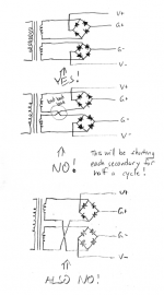
[nothing wrong with blowing things up, just try to learn something from each puff of magic smoke]
An externally hosted image should be here but it was not working when we last tested it.
An externally hosted image should be here but it was not working when we last tested it.
An externally hosted image should be here but it was not working when we last tested it.
Here is some pics of the wiring, quite large mind. The wiring on the bottom pic looks wrong but it is fine, the wires just curl under the board (ground goes to the case, not the board).
Replaced another couple of diodes after a spark and a diode which now looks to have a split case. As a couple of people have mentioned it might be another component causing the diodes to blow but all of them test fine for continuity and it did work before (albeit only in half wave I think).
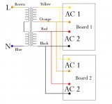
they way you've color coded your secondaries, there's no way to tell if they're being wired properly. Eg, if AC1 / !AC1 are not coming from the same secondary, that's why you're blowing up diodes.
You've got both secondaries as red/black and then both as blue/brown. They're not interchangable. Check that. I'll bet you're mixing the secondary connections and that will both short the transformer (making it growl) and blow diodes. In fact, I'll bet money on it.
Monty
You've got both secondaries as red/black and then both as blue/brown. They're not interchangable. Check that. I'll bet you're mixing the secondary connections and that will both short the transformer (making it growl) and blow diodes. In fact, I'll bet money on it.
Monty
I do apologise for the slightly ambiguous wiring colours but I have checked them over and over and they are definitely correct. I'm really unsure as to what the problem might be now. I had it happen before and just gave up and went with one power supply but i'd really like to find out what wasn't working this time. Will get a nice bright light behind it and check for shorts next i think.
phresh said:I do apologise for the slightly ambiguous wiring colours but I have checked them over and over and they are definitely correct. I'm really unsure as to what the problem might be now. I had it happen before and just gave up and went with one power supply but i'd really like to find out what wasn't working this time. Will get a nice bright light behind it and check for shorts next i think.
If you say you can run each board by itself then I doubt you have a short. You only seem to have a problem when the boards are linked together. Please look at the attached picture and make sure that AC1 on both boards connects to the same pair of wires at the traffo..(AC1 on both boards should connect to the orange/yellow pair).
If this wiring is correct, you will have to disconnect the wires from the rectifier boards to the amps and see if the problem still exists.
Attachments
I just gave up in the end and went with a single rectifier board as i've gota couple of other projects coming up that I want to get on with. The wiring was definitely correct but diodes were failing left right and center in one of the power supplies. All works now .
I really appreciate all the help and advice but this time it wasn't to be Onwards to the next project which thankfully will be a bit easier!
.I really appreciate all the help and advice but this time it wasn't to be
Onwards to the next project which thankfully will be a bit easier!phresh said:I just gave up in the end and went with a single rectifier board as i've gota couple of other projects coming up that I want to get on with. The wiring was definitely correct but diodes were failing left right and center in one of the power supplies.
If the wiring was correct, you wouldn't keep blowing up diodes. Actually, if you were using a lightbulb like AndrewT always suggests, you wouldn't blow diodes either. [To be fair, I don't use a light bulb tester. I also don't make wiring mistakes. ;-]
I had another easy test for you to run with the voltmeter, but it's too late now. There are no unknowable mysteries... besides, if you din't figure out what your mistake was, how do you know you won't make it again later? Maybe the wiring was fine, but you had a short to the chassis somewhere or something like that?
I wouldn't leave something powered and unattended in my own house unless I understood absolutely everything about it...
- Status
- This old topic is closed. If you want to reopen this topic, contact a moderator using the "Report Post" button.
- Home
- Amplifiers
- Chip Amps
- Dual-mono chipamp (3886) problem - possible grounding issue