You can do it with a doubler too. Take the voltage off of the top and out of the middle of your two doubler caps. If you have a 1000v secondary and are using a bridge rectifier the secondary needs to be center tapped:
Ah, thanks Mel! Seeing the schematic clears it up. In case of the doubler circuit i wouldn't even need the center tap, would I?
Hi !
Mel answered already. This could be done with a doubler supply as well as Mel described. No center tap needed in case of the voltage doubler, only with the full wave bridge rectifier.
Thomas
Hi Thomas!
But I won't get away with a fullwave rectifier, this needs a bridge, right? Otherwise the smaller of the two voltages is just connected to one diode.
I have just done some tests with "small", but hi-gm tubes.
Two tested were Soviet pentodes (but triode connected) 6j11p and 6j9p, two triodes 6s3p and 6s45p-e and one triode-pentode 6f12p.
All of these were used together with active load done with NFET.
In general, all of these can produce over 200 Vpp with THD below 0,1 % to 0,5 % depending on the type. Used +Ub was 400 V.
I would like to see what sort of THD results others have got with power tubes as drivers.
Once you consider the load from the 211 grid in the positive grid region the CCS load will help you less and less and you can forget those THD figures if the effective load in your similations was very high!
The effective load seen by the driver will drop (being dominated by the 211 grid) and if the device is not linear and cannot give enough peak current you will get a lot of distortion. The other important requirement for the driver is low Zout but this becomes really important only if the A2 drive is deep. For mild Class A2 will not create issues as long as the driver has headroom and is linear.
Hi kaputt,
I have only done this with a full wave bridge and a transformer with center tap so far.
Thinking about it, I would probably not do this with the voltage doubler as it loads the cap stack asymmetricly.
So yes use a full wave bridge and a transformer with center tap. The driver voltage can be derived from the center tap then through its own filter chain.
Best regards
Thomas
But I won't get away with a fullwave rectifier, this needs a bridge, right? Otherwise the smaller of the two voltages is just connected to one diode.
I have only done this with a full wave bridge and a transformer with center tap so far.
Thinking about it, I would probably not do this with the voltage doubler as it loads the cap stack asymmetricly.
So yes use a full wave bridge and a transformer with center tap. The driver voltage can be derived from the center tap then through its own filter chain.
Best regards
Thomas
Hi!
I built around a dozen 211 amps with all kinds of drivers. Among them high gm triodes. Those were the worst. I do like high gm triodes and use them a lot in phonostages but not as driver tubes
Thomas
I think the problem with many high Gm devices with CCS (or other high loads) when one takes the output from the anode is that their gain will drop significantly entering A2. Their low plate resistance will not help much.
Also many of those high GM devices can only work at relatively low plate voltage and so there is no headroom for large voltage swings + power drive. Actually those that cannot work at more than 200V are not even good as cathode followers!
Hi!
Exactly! That's what I keep saying. People often choose these high gm tubes as drivers so they need only two stages in an amp. While I am all for minimizing the number of gain stages, in this case this is the wrong approach. Sometimes things can get too simple and thus compromised
Best regards
Thomas
IAlso many of those high GM devices can only work at relatively low plate voltage and so there is no headroom
Exactly! That's what I keep saying. People often choose these high gm tubes as drivers so they need only two stages in an amp. While I am all for minimizing the number of gain stages, in this case this is the wrong approach. Sometimes things can get too simple and thus compromised
Best regards
Thomas
I recently started tinkering with my DIY 211 amp(s) lately (mono blocks) and came across this thread.
When I initially designed the driver circuit, I wanted a simple circuit for two reasons;
1. To see (and hear) how well a small signal tube could actually drive the grid of these big power tubes despite all the "simulations" being done.
2. To keep the circuitry simple as to maybe attract other people to experiment with big power tube amps.
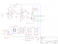
My driver consists of a 6SL7GT (paralleled) in a standard grounded cathode topology direct coupled to a 6SN7GT (paralleled) emitter follower.
B+ for the driver circuit is about 455VDC which puts the 6SL7GT at the maximum plate rating of 250VDC. With this operating point for the voltage amp / cathode follower I can easily get 200V P-P to drive the 211 grid.
With @1080VDC on the plate of the 211, biased at about 64mA (16k output transformer) I am getting 17.5 WRMS @ 5%THD+N. This is due to the driver circuit reaching its limitations.
I'll post a schematic of the driver circuit soon. I had it on my hard drive, but can't find it now, so I'll redraw it.
Nick
When I initially designed the driver circuit, I wanted a simple circuit for two reasons;
1. To see (and hear) how well a small signal tube could actually drive the grid of these big power tubes despite all the "simulations" being done.
2. To keep the circuitry simple as to maybe attract other people to experiment with big power tube amps.
My driver consists of a 6SL7GT (paralleled) in a standard grounded cathode topology direct coupled to a 6SN7GT (paralleled) emitter follower.
B+ for the driver circuit is about 455VDC which puts the 6SL7GT at the maximum plate rating of 250VDC. With this operating point for the voltage amp / cathode follower I can easily get 200V P-P to drive the 211 grid.
With @1080VDC on the plate of the 211, biased at about 64mA (16k output transformer) I am getting 17.5 WRMS @ 5%THD+N. This is due to the driver circuit reaching its limitations.
I'll post a schematic of the driver circuit soon. I had it on my hard drive, but can't find it now, so I'll redraw it.
Nick
I'm building a 211 tube amp and I don't know to driver the 211 with EL34 or VT-25. personal preference is VT25 but I want your idea")
FPQ1N50
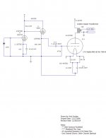
You can't beat a power MOSFET source follower as a grid driver, especially for these power triodes. It has more than enough current sourcing to drive the CMiller and to take care of grid current, and these power finals will draw grid current even before Vgk > 0.
With the schematic I posted a few measurements are:
Frequency Response: 11Hz ~ 26kHz, -3dB
THD+N: 1 Watt, 4 Ohm, 0.22%
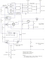
Nick:
Thanks for posting the schematics. Is there any particular reason you show a 6F8 on the schematic. I think it is a single triode that predates the 6SN7, correct?
TNX, Mike
Last edited:
Back in 1999 when I was "accumulating" NOS tubes, I thought they looked nice/retro and they were inexpensive, so I bought some. My 211 mono block amps have a "retro rack mounted theme" and the 6F8G helps preserve this look.
The 6F8G is very similar to the 6SN7, but not identical. The 6F8G is a twin triode, but one of the grids is on top of the tube. Also, the pin-out is different from the 6SN7 type tube.
The 6F8G is very similar to the 6SN7, but not identical. The 6F8G is a twin triode, but one of the grids is on top of the tube. Also, the pin-out is different from the 6SN7 type tube.
Back in 1999 when I was "accumulating" NOS tubes, I thought they looked nice/retro and they were inexpensive, so I bought some. My 211 mono block amps have a "retro rack mounted theme" and the 6F8G helps preserve this look.
The 6F8G is very similar to the 6SN7, but not identical. The 6F8G is a twin triode, but one of the grids is on top of the tube. Also, the pin-out is different from the 6SN7 type tube.
Since the 6SN7 is a dual triode, what would be wrong with using each section separately, as per your schematic?
If you use a single 6SN7 for gain and cathode follower, you will not have enough gain to drive the grid of the 211 tube to "full" power.
Technically, it would work.
You could also cascade each section (With no cathode follower) and drive the 211 tube. This would give you enough gain/drive to achieve full power from the 211.
This has been done before and schematics showing use of it are out there in cyberspace.
Technically, it would work.
You could also cascade each section (With no cathode follower) and drive the 211 tube. This would give you enough gain/drive to achieve full power from the 211.
This has been done before and schematics showing use of it are out there in cyberspace.
- Status
- This old topic is closed. If you want to reopen this topic, contact a moderator using the "Report Post" button.
- Home
- Amplifiers
- Tubes / Valves
- Driving 211 with VT25 or EL34?