Lynn Olson said:
I'll be doing subjective listening of the 414/Alnico, TD12M, and the 18Sound 12NDA520, with a primary focus on naturalness of the midrange with solo voice and choral music. Although the nominal crossover is 800 Hz, I don't plan on slopes any steeper than 12 dB/octave, so the quality above 800 Hz remains important. This is the same philosophy as the Ariel - each driver has to be natural-sounding without high-slope filtering to reject breakup regions.
I think that (and getting the average 1 watt 1 meter you want), will be by far the most critical to the overall design. I think this "encompasses" linear decay which wasn't presented, so there could be some more testing to do.


Who knows, you could go "full-circle" and end-up with the Tone Tubbys.

fb said:Nick, what would the apollo upgrade do for the IMD on the TDMs?
I'm curious about the power compression for the TDMs too, hope to see that and the measurements for the 15"
I don't know to be honest. The Apollo did lower the Le some more on the M models, you could hear it in the midrange. The Apollo would show more gain on the long coil models I would think (S,X,H) when compared to a standard TD motor.
I am waiting for the TD15M measurements myself, that is one of my favorite drivers.
ScottG said:
I think that (and getting the average 1 watt 1 meter you want), will be by far the most critical to the overall design. I think this "encompasses" linear decay which wasn't presented, so there could be some more testing to do.
Who knows, you could go "full-circle" and end-up with the Tone Tubbys.
I've heard enough high-slope-crossover digitally equalized dipoles to know that is the direction I don't want to go. I'm fine with parametric EQ (and Class AB transistor power amps) below 200~300 Hz, where it can do a lot of good to compensate for the worst of room problems, but I really don't care for what it does to the sound above that.
Certainly not ruling out the TT's by any means. But I expect it'll come down to an alliance of Altec and AESpeaker technology, based on what I've heard so far. And once that's done, that's 80% of the project right there: smooth-sounding drivers with well-behaved breakup regions, and ample headroom and efficiency.
Not the same drivers as the Ariels, but a similar design philosophy. The Ariels were a 5 dB jump in efficiency compared to the ones I was listening to before, and the new system will be 5~8 dB more efficient compared to the Ariels.
Lynn Olson said:Not the same drivers as the Ariels, but a similar design philosophy. The Ariels were a 5 dB jump in efficiency compared to the ones I was listening to before, and the new system will be 5~8 dB more efficient compared to the Ariels.
I went the same route myself, once I heard clean and smooth higher efficiency it was hard to listen to 87dB@1W speakers anymore.
Same for Class A amplification. Once you hear it, you don't go back.
Makes sense: high-efficiency, low-energy-storage loudspeakers, and inherently linear amplification. Much better than the alternative: low-efficiency loudspeakers (with 99+ % of the power wasted in heating the voice coil), and Class AB or D amplification, with device-switching in the direct signal path. People forget that classical feedback theory assumes a linear forward path; it breaks down when you add switching devices.
Audiophiles obsess about little things like corrosion on wires and connections: how about gross nonlinearities in electronics and drivers? Better to work at the level of device fundamentals (magnetic field geometry, standing waves, diffraction, and electron-device physics) than get lost in the weeds of second-order effects.
nickmckinney said:
The pole vents through the dustcap as they use a solid piece of steel for the top center pole piece (on top of the Alnico) This was common back in the day, most other drivers like this used a fully screened dustcap. Its either this or no dustcap (like our TD drivers)
Have you ever considered attempting to apply a screen 'dustcap' over the TD drivers? Eminence did this with the Magnum series, an acoustically transparent mesh dustcap to keep any gunk out of the gap, and it also took a little of the 'bling' factor down with the 4" diameter phase plug. It might be a nice option, I think the TDs are clearly fantastic drivers, but the phallus in the middle is a little much for me, something to hide it a little without going to a 'grille' proper' might be a nice touch for some users.
Lynn Olson said:Same for Class A amplification. Once you hear it, you don't go back.
I think you'd have an impossibly hard time getting that past an engineer like Geddes or Linkwitz (or anyone who knows better). This has been tossed around forever but the bottom line is that a 'good amplifier' cannot be distinguished from any other 'good amplifier'. At least not by listening to it's output.
badman said:
Have you ever considered attempting to apply a screen 'dustcap' over the TD drivers? Eminence did this with the Magnum series, an acoustically transparent mesh dustcap to keep any gunk out of the gap, and it also took a little of the 'bling' factor down with the 4" diameter phase plug. It might be a nice option, I think the TDs are clearly fantastic drivers, but the phallus in the middle is a little much for me, something to hide it a little without going to a 'grille' proper' might be a nice touch for some users.
Its no problem to do this if someone really wanted it that way. You lose some of the heatsinking would be all.
How about its effect on dispersion in higher range (in real life)? Or, the physical size of the phase plug is too small for their ranges?
For reference, I found these drivers very interesting (,too):
This comes with a mesh dust cap:
http://www.supravox.fr/anglais/mesures/mes285GMF1.htm
This comes with a phase plug:
http://www.supravox.fr/anglais/mesures/mes285_20001.htm
To my eyes, the one with mesh dust cap has a dip at 1.7-1.8kHz or so (on and off axis), but can't comment it's exactly the effect of cap/plug....
Update to the site:
Removed the THD values from the spectrum analyzer pics so they didn't cause confusion. Removed the THD scale from the HD sweep because it was the wrong scale and I like dB scales better. Added the Impulse Response to the frequency response pages. This is the IR of the 1m on axis measurement. These are NOT as intuitive to read as I once thought. If you don't understand the subtleties of what an IR shows don't even bother looking at these. These are extremely difficult to standardize so they are directly comparable to each other. So beware. I also started adding some compression driver info as I just started the horn testing.
Removed the THD values from the spectrum analyzer pics so they didn't cause confusion. Removed the THD scale from the HD sweep because it was the wrong scale and I like dB scales better. Added the Impulse Response to the frequency response pages. This is the IR of the 1m on axis measurement. These are NOT as intuitive to read as I once thought. If you don't understand the subtleties of what an IR shows don't even bother looking at these. These are extremely difficult to standardize so they are directly comparable to each other. So beware. I also started adding some compression driver info as I just started the horn testing.
Just copying my post over from AVS as well as it is general info.
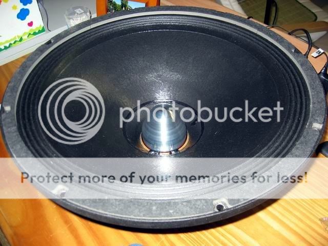
The impulse response is another tool,along with the impedance curve and frequency response, that you can use to get a general idea of what is going on in a driver. As an example of a driver that has some obvious things, look at the GPA414. In the impedance curve you see a couple blips. One at about 170hz or so, a small one at about 600hz, then another series of blips starting about 1500hz. You can look at those same regions in the nearfield response and notice dips or peaks at the corresponding frequencies. This indicates that there are some kind of resonance issues going on at those points. Typically you'll have a cone resonance, surround resonance, spider resonance and dustcap resonance all to address.
The impulse response then can tell you how significant the resonances may be. Looking at the 414 IR, you can see the 2 initial larger peaks, followed by a quick decay, and then the impulse actually increases in magnitude later on. This is indicating that some "stored energy" for lack of better term is being released further on.
Initially a thought would be that this kind of impulse in a cabinet means a reflection off a back surface in the box. That should however show in any drivers measured in the same conditions. My guess which is still somewhat a shot in the dark without seeing a CSD plot would be this. Two resonances that start somewhat out of phase from each other and at first somewhat cancel. One resonance decays faster than the other, allowing the second to increase in magnitude slightly further on, leading to the increase in the impulse. An example of something that could happen this way would be a dustcap and spider which have similar diameters, each having a resonance, but with very different damping.
Had you thought of posting CSD plots? They should be easy to generate if you have an impulse response.
John
CLS said:How about its effect on dispersion in higher range (in real life)? Or, the physical size of the phase plug is too small for their ranges?
For reference, I found these drivers very interesting (,too):
This comes with a mesh dust cap:
http://www.supravox.fr/anglais/mesures/mes285GMF1.htm
This comes with a phase plug:
http://www.supravox.fr/anglais/mesures/mes285_20001.htm
To my eyes, the one with mesh dust cap has a dip at 1.7-1.8kHz or so (on and off axis), but can't comment it's exactly the effect of cap/plug....
We found a problem with the plug on the Apollo driver as the plug from the TD became too short on that motor. It caused IM distortion in the midrange that you could hear instantly. Hence the longer johnny "Johnny Holmes" plug was created and problem solved.
A mesh dustcap will become a mild radiating surface so there will be some negative change in the midrange. How much and how significant is hard to say without trying it.
Brandon,
One possible typo on your awesome drivervault site. You have, listed in the tweeter section, the B&C DE12 with mylar diaphragm. Do you mean DE10? The DE10 is mylar, the DE12 is a titanium diaphragm afaik.
I was a bit surprised by the impedance of the DE1*. It doesn't show the dual hump like the others. Very interesting.
I pulled the IR because they are just causing confusion. I did make an attempt at one point adjust the output level for the response measurements so that all the drivers would about the same level in their midband. I'm going to look at these to see if they would be better candidates to post.
You know I used to, and I probably will for these. No rush as I have the IR so I can do it anytime. My only problem as these are often as misleading as comparing IR's. So I dunno...I have to think about. There are many factors which MUST be standardized (at least in my mind) before any two IR really comparable, especially when looking for signs of resonances and such.
B&C makes both versions. The mylar version is available at both usspeaker and prosoundservice. I picked the mylar for a project I'm doing that needs to behave nicely on the low end as I'll be running it a lower than the spec'ed crossover frequency.
Actually I was surprised that the others had two peaks. In my VERY simple understanding of CD's one hump is the drivers resonance and the other is the horn resonance, which is almost always attached for the manufacturers' impedance plot. Someone more knowledgeable will hopefully chime in on that.
John_E_Janowitz said:Had you thought of posting CSD plots? They should be easy to generate if you have an impulse response.
John
You know I used to, and I probably will for these. No rush as I have the IR so I can do it anytime. My only problem as these are often as misleading as comparing IR's. So I dunno...I have to think about. There are many factors which MUST be standardized (at least in my mind) before any two IR really comparable, especially when looking for signs of resonances and such.
JoshK said:Brandon,
One possible typo on your awesome drivervault site. You have, listed in the tweeter section, the B&C DE12 with mylar diaphragm. Do you mean DE10? The DE10 is mylar, the DE12 is a titanium diaphragm afaik.
I was a bit surprised by the impedance of the DE1*. It doesn't show the dual hump like the others. Very interesting.
B&C makes both versions. The mylar version is available at both usspeaker and prosoundservice. I picked the mylar for a project I'm doing that needs to behave nicely on the low end as I'll be running it a lower than the spec'ed crossover frequency.
Actually I was surprised that the others had two peaks. In my VERY simple understanding of CD's one hump is the drivers resonance and the other is the horn resonance, which is almost always attached for the manufacturers' impedance plot. Someone more knowledgeable will hopefully chime in on that.
Results of teh horns going up now. I have ALOT more data to post but thought I'd give you taste. I think I have a couple good candidates for driver comparisons so for short time I'm going to keep testing IF some helpful members would send the following: Beyma CP380M, Beyma CP385ND, BMS 4550, or the top 18 Sound CD's. These tests will include distortion.
nickmckinney said:
We found a problem with the plug on the Apollo driver as the plug from the TD became too short on that motor. It caused IM distortion in the midrange that you could hear instantly. Hence the longer johnny "Johnny Holmes" plug was created and problem solved.
...
Alas!
I got some custombuilt phase plugs for my 18" woofers:

I've not yet tested them.
The de-cap'ed woofers sounded fine without the plugs, just uglier. It'll be a disaster if the plugs make them sound worse
CSD and IR data added for woofers and horns. Careful with interpreting the IR. People may be tempted to see a bit more wiggle in the tail and say that is a sign of stored energy or it's ringing. It may just have higher low frequency response. The IR oscillates and the amplitude of the peaks/dips is mostly an indication of the SPL at the frequency that coincides with the length of time in the scale. What I look for is narrow peaks/dips that are out of place, or out of "rhythm"
- Status
- This old topic is closed. If you want to reopen this topic, contact a moderator using the "Report Post" button.
- Home
- Loudspeakers
- Multi-Way
- Driver testing results