Hi jReave,
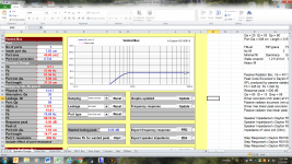
Yes, I'm will be using the Dayton RS150 paper version in 8 ohm. I attached a screenshot from unibox using Dayton RS150P trying to model aperiodic behavior. I remember reading somewhere that Ql= 3-5 comes close represented an aperiodic enclosure. Can't recall who mentioned that. If you feel that is to low we can adjust to a higher value.
Thanks for the compliment; I try to read threads of interest on this forum and spend considerable time on Troels Gravesen's website. I like his practical approach to speaker design/building. As for design decisions, please let me know if any areas can be improved upon.") I tried to pay attention to things like center to center spacing between mid and woofer(s) being with 1/4 wavelength at crossover frequency (280-300 hz seems close?). Driver height from floor may be a few inches to high @ 27 inches, but a compromise had to be made between floor bounce theory and mid/woofer c-c spacing. I see why building speakers always contains a compromise or two.
I tried to pay attention to things like center to center spacing between mid and woofer(s) being with 1/4 wavelength at crossover frequency (280-300 hz seems close?). Driver height from floor may be a few inches to high @ 27 inches, but a compromise had to be made between floor bounce theory and mid/woofer c-c spacing. I see why building speakers always contains a compromise or two.
On a different note, my brandy spanking new Bosch router arrived today. My old Craftsman router was having bit slipping issues that rendered it useless. Before I plunge it into a baffle, I will make sure we are good to go and no changes to layout is needed.
BTW, great news on the off-axis breakthrough in Xsim.
Again, thanks so much for your willingness to take this journey with me!
Best,
Rich
Yes, I'm will be using the Dayton RS150 paper version in 8 ohm. I attached a screenshot from unibox using Dayton RS150P trying to model aperiodic behavior. I remember reading somewhere that Ql= 3-5 comes close represented an aperiodic enclosure. Can't recall who mentioned that. If you feel that is to low we can adjust to a higher value.
Thanks for the compliment; I try to read threads of interest on this forum and spend considerable time on Troels Gravesen's website. I like his practical approach to speaker design/building. As for design decisions, please let me know if any areas can be improved upon.
I tried to pay attention to things like center to center spacing between mid and woofer(s) being with 1/4 wavelength at crossover frequency (280-300 hz seems close?). Driver height from floor may be a few inches to high @ 27 inches, but a compromise had to be made between floor bounce theory and mid/woofer c-c spacing. I see why building speakers always contains a compromise or two.On a different note, my brandy spanking new Bosch router arrived today.
My old Craftsman router was having bit slipping issues that rendered it useless. Before I plunge it into a baffle, I will make sure we are good to go and no changes to layout is needed.BTW, great news on the off-axis breakthrough in Xsim.
Again, thanks so much for your willingness to take this journey with me!
Best,
Rich
Attachments
As I said, aperiodic modeling is new to me so I just wanted to check that you had some reference for what you were doing. If that's what's recommended then Ql = 3 seems just fine.
So far my only suggestion is primarily aesthetic - I don't like the look when the transition between top and bottom cabinet on the sides isn't smooth. But that's just me. I might consider adding another panel to the sides of the top cab and/or also putting a bevel on the bottom cab's top side edges and/or maybe adding just a partial side panel as Troels has done for many of his big 3- and 4-way floorstanders. You get to be artistic - whatever looks best to you. Or maybe you have something like this planned already and you were just waiting for your new router.
So far my only suggestion is primarily aesthetic - I don't like the look when the transition between top and bottom cabinet on the sides isn't smooth. But that's just me. I might consider adding another panel to the sides of the top cab and/or also putting a bevel on the bottom cab's top side edges and/or maybe adding just a partial side panel as Troels has done for many of his big 3- and 4-way floorstanders. You get to be artistic - whatever looks best to you. Or maybe you have something like this planned already and you were just waiting for your new router.
Hi jReave,
Good eye for detail. I'm still undecided on improving the transition you mentioned. I do agree attention is required in that area. New router will get run through the paces on Monday. I'm going to temporarily attached baffle that is pictured above to cabinet and run a 1/2" shank x 2 1/2" flush trim router bit along the edges. I need to trim approximately 1/4" from all sides. Lots of fun stuff to get into.
Best Regards,
Rich
Hey Rich,
I've now gone through process and figured out that there is a little trap in PCD when working with sloped baffles. I thought it was important enough to start another thread on the topic, http://www.diyaudio.com/forums/multi-way/302669-modeling-sloped-baffles-pcd-xsim.html.
Give it a read and then I'll carry on with my suggestions for yourself.
One thing I need to know though is how you want to proceed. Do you want to work through the process that I'll outline again yourself or would you like me to just attach the new files that I've come up with?
I'm running out of gas tonight so I'm just going to attach a few relevant pieces of info which you can play with if you have time and I can explain a little more about tomorrow.
First, my frd and zma files. Change .txt back to .frd and .zma. I like to always double check my work which I haven't done yet so be prepared, there may in fact be changes to come. And if you do change the dimensions of the top cab, all the diffraction sims should be revisited again too. (FRC means Frequency Response Combiner which is the program I use for combining FR's and extracting min phase)
I used Zaph's measurements for the tweeter btw.
You need to make sure that you set up either PCD or XSim with 2 woofers and that you input the data for both of them. The FR's are different for each because diffraction is different but impedance is the same for each one.
Attachments
-
FRC twtr + 15dgr dfrctn.txt12.7 KB · Views: 29
-
FRC mid @ 15dgr dfrctn.txt31.8 KB · Views: 28
-
FRC top wfr.txt31.7 KB · Views: 25
-
FRC btm wfr.txt31.6 KB · Views: 23
-
wfr Z + phase VB 60L Fb=30Hz modified.txt13.1 KB · Views: 33
-
mid Z + phase CB 12L Ql=3 modified.txt13.1 KB · Views: 25
-
twtr raw Z + phase by zaph sample 1.txt24.4 KB · Views: 33
The following attachments should help with the set up of either PCD or XSim.
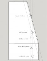
1) shows how I arrived at the relative acoustic offsets.
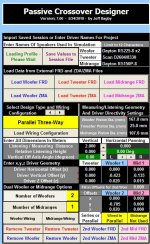
2) is how to setup PCD
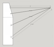
3) is how to arrive at the mod delays for XSim (mid= -.1875"; top woofer=+2.641"; and the bottom woofer=+8.188")
You should double check my work as it's getting easier to make mistakes when I get tired these days.
I reached out elsewhere btw for the measured acoustic centers for your mid and woofers because they can easily be a little different than using a physical location on the actual driver. I got 33mm for the mid and 53mm for the woofers. Subtract 5mm each for the tweeter's acoustic center.
When you are working on a xo, using target filters is very, very helpful, especially when you are just starting out. I'm going to suggest 2nd order LR2 acoustic slopes for everything at about 400Hz and 2500Hz. One of the nice things about PCD is that this function is built in. In XSim you need to create the target slopes yourself. I use Response Modeler to create them and then in XSim I'll create new drivers for each target and import them as the drivers FR. You do not attach these drivers electrically to the amp in XSim, you use the display function in the FR chart ("Curves --> driver only") to show them when you need them.
Hopefully that's enough to get you started.
1) shows how I arrived at the relative acoustic offsets.
2) is how to setup PCD
3) is how to arrive at the mod delays for XSim (mid= -.1875"; top woofer=+2.641"; and the bottom woofer=+8.188")
You should double check my work as it's getting easier to make mistakes when I get tired these days.
I reached out elsewhere btw for the measured acoustic centers for your mid and woofers because they can easily be a little different than using a physical location on the actual driver. I got 33mm for the mid and 53mm for the woofers. Subtract 5mm each for the tweeter's acoustic center.
When you are working on a xo, using target filters is very, very helpful, especially when you are just starting out. I'm going to suggest 2nd order LR2 acoustic slopes for everything at about 400Hz and 2500Hz. One of the nice things about PCD is that this function is built in. In XSim you need to create the target slopes yourself. I use Response Modeler to create them and then in XSim I'll create new drivers for each target and import them as the drivers FR. You do not attach these drivers electrically to the amp in XSim, you use the display function in the FR chart ("Curves --> driver only") to show them when you need them.
Hopefully that's enough to get you started.
Attachments
Thanks jReave,
I got all files downloaded and installed in PCD. Just wanted to double check if you simulated woofers in sealed cab or ported? I had noticed 30 hz. in file description. I would very much like to go ported for max low end extension but, it did not seem possible in Unibox to achieve from 62 liter enclosure. Also, did you go with the SS D2604/8330 or the R2604/8330 version. Thanks to Madisound mishaps, I'm the proud owner of (1) each. So, either way, I will need to purchase another to make a pair. Well, I'm going to work awhile this evening on plugging in some Xo values and see what I can come up with.
Best,
Rich
Hi jReave,
I been modeling dual woofers in Unibox this evening. It indeed looks like a ported alignment would work excellent. There is only a minimal peak at 64 hz. An F3 of 33 hz would be outstanding (no sub woofer required). I'm not sure why I thought much larger volume was needed in order to go the ported route. Anyway, this is good news! Also, I have made good progress with a XO design in PCD. I'm not sure of the best way to attach .csp file for you to critique.
Best,
Rich
I been modeling dual woofers in Unibox this evening. It indeed looks like a ported alignment would work excellent.
There is only a minimal peak at 64 hz. An F3 of 33 hz would be outstanding (no sub woofer required). I'm not sure why I thought much larger volume was needed in order to go the ported route. Anyway, this is good news! Also, I have made good progress with a XO design in PCD. I'm not sure of the best way to attach .csp file for you to critique. Best,
Rich
Yes, I assumed you would want to go ported. Even though 60L is smaller than the optimal, it still looked good enough to me. Just make sure that 60L or so is your net volume after subtracting bracing and port, driver and xo (unless you go external) volumes.
Your 2 tweeters look very similar on all kinds of parameters but I haven't heard either one. However the Scan ring radiator is the tweeter that the Vifa XT25 is based on and I do have experience with that one. A very nice tweeter so I expect the Scans to be just as good if not a little better.
The one area they do look to differ though (according to manufacturer's specs) is in the off-axis responses and since you are using a sloped baffle here and the D2604 has the better off-axis response, I would probably stick with that one. But they do actually look to be so close to each other I think you might be able to just swap them back and forth without changing the xo to see if you notice any difference or prefer 1 to the other.
In terms of viewing PCD here, you can easily export the summed response and impedance charts as well as take screen shots of the xo sections and attach those. It's easy for me to then plug those values into my program since we're working with the same files.
Otherwise I think you need to go to email to attach an Excel program without changing it. I can't remember if you can do that in a Private Message too but I don't think so. Maybe you can zip it up and attach it that way but I've yet to figure out how to do that.
Or you can always set up XSim too and attach that in 1 form or another. That's next on my list today, is to set it up and double check that those delay values are correct.
I reached out elsewhere btw for the measured acoustic centers for your mid and woofers because they can easily be a little different than using a physical location on the actual driver. I got 33mm for the mid and 53mm for the woofers. Subtract 5mm each for the tweeter's acoustic center.
Rich,
I was checking a couple of things this morning and have discovered my 1st little mistake, above.
When I calculated the relative acoustic offsets for your sloped baffle I used the relative acoustic centers for the mid and woofers on a flat, vertical baffle, which is incorrect (33mm and 53mm each minus 5mm for the tweeter). Force of habit that one is. Instead I should have used the absolute acoustic centers of each driver to make the calculations.
This means then that the real acoustic centers of the mid and woofers will be backwards another 5mm, so relative to the tweeter, the mid z-offsets in PCD should be 10mm and 15mm for the woofers. So all acoustic centers end up a little more closely aligned on the vertical axis, which is more or less the whole purpose of the sloped baffle in the 1st place.
I kind of expected this to bring the phase closer into alignment when choosing 2nd order electrical xo's for your tweeter and mid but in fact the opposite is true, which makes it just a little bit harder to work with. Harder but not impossible.
Sorry about that.
- Status
- This old topic is closed. If you want to reopen this topic, contact a moderator using the "Report Post" button.
- Home
- Loudspeakers
- Multi-Way
- Driver polarity Question