It just hit me today because of another post on another thread that the part or the voice coil in the gap is the motor in a model and the part of the voice coil not in the gap is an inductor. The voice coil not in the gap does not produce significant back EMF. Because no back EMF is produced that part of the voice coil is an inductor in the model and not part of the reflected impedance
My understanding is that the inductance of the voice coil is that of the complete coil, both the "air cored" parts outside the gap and the "iron cored" part inside the gap. (Think of a driver with the voice coil glued into the gap.) The back EMF is a separate entity, generated from movement of the coil in the gap, which is in turn influenced by the driven mass, compliance etc.
I've seen it argued that a driver can't be accurately (SPICE) modeled because it doesn't allow for external influences on the driver - for example, reflections from the walls of an enclosure making the diaphragm move, generating an EMF. In fact, these can be modeled with delays and filters. Other non-correlated influences, such as environmental noise, can be modeled with voltage sources. It depends on how accurate you want the model to be.
Talked with the other driver designer today and we decided if an 8 ohm resistor was place across a nominal 8 ohm speaker of a stereo pair and the other speaker was driven a "speaker as a detector" data could be measured with any form of analyzer one would care to use. This acoustic to electrical drive data could go into the rest of the electrical model as delayed signal sources into other inputs (new ones) for the acoustic signal..
The acoustic signal (for the mono which is on both left and right) really is a delayed signal from the second speaker driving the first speaker. Is this a better approximation than a noise source? Think so as one speaker moves against the other speaker when the same (mono) signal exist in both channels.
I have shown I can greatly reduce the cone motion of an active first woofer if the second woofer is connected through an adjustable delay by adjusting that delay. Of course this demonstration was done with a steady state sine signal but still...
Is this a really bad idea or is it worth checking? We though next time the test system is set up we'd have a look? Made us both curious.
I can't remember where i found this zip but I hope it's OK to attach it.
If not then remove it.
I have not looked at it that close but it seems very nice and complete.
Found this thread while surfing around...
That zip file with the models is mine; and actually my name and email are in the html page instructions that is included in the zip file that tells in detail how to use the model files.
I don't mind it uploaded here, as long as my name is included as credit. Because it was not small amount of work making them and verifiying their functionality, even though the main work was done by Prof. Leach. I still have the file is still here (after the annoying ad page):
http://members.fortunecity.com/pirimoglu/SpeakerSpiceModels.htm
It just hit me today because of another post on another thread that the part or the voice coil in the gap is the motor in a model and the part of the voice coil not in the gap is an inductor. The voice coil not in the gap does not produce significant back EMF. Because no back EMF is produced that part of the voice coil is an inductor in the model and not part of the reflected impedance
Hope this helps.
In August 2005 I had sat down and modeled the voice coil as a transformer with shorted secondary windings with leakage induction (the part not in the gap, more precisely the part that is not fully coupled to the rest of the transformer etc..) I had written a lengthy document on this and posted and uploaded this to a couple of audio forum sites at that time.
The document is still available from here:
http://members.fortunecity.com/pirimoglu/
(Click on the link "Faraday (shorting) rings and their effect on voice coil impedance and benefits in terms of reduction of nonlinearities"...)
As far as I know, this was a novel idea (at least for me) at the time, had not seen anywhere before used this way: to model the loudspeaker motor as a transformer with leakage inductance etc. that accounts for eddy currents and if used shorting rings.
Coming back to context of the thread, in the SPICe models, the inductance part of the loudpspeaker can be changed into three mutually coupled inductors (3 windings of transformer) with two windings having a resistance shorting them, and having less than a coupling ratio of 1, and the effects off loss inductance of real loudspeakers can be simulated in SPICE.
Towards the end of the document I mentioned above I give examples of these in SPICE and how they can be used to model real world inductance of loudspeakers.
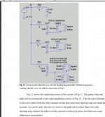
Attach is a screen shot from a page from the document, Lvc3 is the voice coild inductance in free air, Lsr3 is shorting rings inductance, Lpole3 is pole and other surrunding iron's inductance to account for eddy currents. Rsr3 is the resistance of shorting ring and Rpole3 is representative of the resistance of the eddy currents on iron parts. K30, K31 and K32 are the coupling ratios used. To find the correct values for all these parameters for a real loudspeaker, a curve fitting needs to be done between calculated and measured impedance.
This model doesn't take into account "skin effect".
Attachments
Last edited:
Hi
Not that I have much experience with the modeling of loudspeakers, but the following do seam apparent to me.
There are two things consider.
One thing is to model how the speaker appears electrically, i.e. an equivalent electrical model as you speak of. Another thing is to make this correlate with the acoustic frequency response of a speaker. The electrical part of the 'equation' has a lot to say, but it only gives a relative measure of some of the effects that show of in an acoustic frequency response.
The coupling between the electrical domain and the acoustic/mechanical domain, is very bad, to put it in a nice way. If there's anything, electrically, that affects the impedance (inductance, wire resistance, the skin effect, parasitic capacitance etc. etc.), it will all show up in the acoustic frequency response in a relative manner. However, as the electro-mechanical coupling is low, anything that is explained from the mechanical side of things, will show up in the acoustic frequency response, but will not necessarily show up in the electrical frequency response. Therefore you can predict some phenomenas using a novel equivalent electrical model likes yours + curve fitting, but it's only solves half part of the task. A direct effect of this is that a speaker driven with stiff voltage sounds different than a current driven one. It also explains why cables sometimes could have an influence and why integrated active class D speaker designs solve so many problems at one time (if you don't have a religious view on things, that prevent you from thinking with this kind of mindset. Luckily for some, a lot of customers also approach audio solutions from a religious angle).
Anyway, my point is that, not everything can be predicted with a proper equivalent electrical model, the low electro-mechanical coupling clouds for a lot of the mechanical effects that are apparent if you measure a speakers frequency response.
Btw. I might add that I've moved away from the class D audio business a couple of years ago, to explore the possibilities with piezoelectric-transformers, but I still have a few opinions to share about the subject. I do however, have no financial interests to speak in the favor of active class D loudspeakers.
Best regards Kaspar S. Meyer
Last edited:
- Status
- This old topic is closed. If you want to reopen this topic, contact a moderator using the "Report Post" button.