You might find this interesting...
Hello,
I have designed and been using for quite a while now what has been a very good driver for bridged, BPA, Symmetric, designs. You may be interested in the approach.
http://www.diyaudio.com/forums/showthread.php?postid=1020886#post1020886
more info here:
http://www.twistedpearaudio.com/docs/TX/TX.pdf
and here:
http://www.twistedpearaudio.com/docs/txd/txd-doc.pdf
You can use the driver with a closed loop to drive a balanced amp just like a DRV or similar circuit, or you can enclose the chipamps in the loop and add the compensation caps and you get something considerably better than a common BPA.
Cheers!
Russ
tryonziess said:anyone had any luck with a hot plate and solder paste with smd components. as i get older these parts get smaller and the two do not go together well. since the opa1632 can not be had in dip 8 soldering will be tedious.
I've done it with a toaster oven. It was a while ago, so I can't remember the times or temperatures needed, but it worked excellent.
The big trick was to give the toaster just a little thump when it got to temperature. Not hard enough to displace the parts, but enough that they'll move slightly. The surface tension of the melted solder will pull all the pins into line with the pads.
I've done soic a few times using adapter boards. It's really not that difficult to solder them if you have a good pointy iron.
Very carefully tin all of the pins on the board and the chip. solder wick works well if you screw up. you only want a very thin layer of solder, so that the chip still sits nice and flat, not all tipsy on big solder bumps.
stick it in place somehow and then just touch each pin long enough to stick it to the pad.
ssop is a real pain.
") I've had some limited success hand soldering them by carefully aligning them to the board and soldering them, completely ignoring the fact that they all blob together. (They do have to be well aligned to the pads though)
I've had some limited success hand soldering them by carefully aligning them to the board and soldering them, completely ignoring the fact that they all blob together. (They do have to be well aligned to the pads though)Next you can use some high quality fine solder wick and pick up the excess.
It's pretty hit and miss, and I wrecked some chips, but before I knew about the toaster oven method It was the only way I could do it.
-Nick
banana said:Hi Alexcd,
I suggest u to add a toggle switch, to ground R5 directly when doing unbalance to balance conversion. This should give u lower noise.
I was thinking the same thing! Thanks for the reassurance.
Why the OPA part? It seems that op amps have different sound so I would recommend getting a few selections and see what you like the best. National's LME op amps seem to have some good feedback or the LM4562 has has good comments. Try out 3-4 different ones that seem to be popular and see what you like best. You might be like me and not that discerning and not really hear much difference but it will be fun too.
-SL
-SL
would it be possible to use a lm3886 chip as the driver for a string of bi-polar transistors or mosfets to achieve 600 to 800 watts output. it already has the first stage and driver stage and the specs are outstanding. you would need a separate power supply for the output stage. or is this not possible. would make a nice simple semi-discrete amp.
National has realeased a chip to do exactly that.tryonziess said:would it be possible to use a lm3886 chip as the driver for a string of bi-polar transistors or mosfets to achieve 600 to 800 watts output. it already has the first stage and driver stage and the specs are outstanding. you would need a separate power supply for the output stage. or is this not possible. would make a nice simple semi-discrete amp.
There is a thread running about it now.
Go read.
As Andrew mentions, National has the driver chips LM4702 and LME49810. The LM4702 was the first and is a stereo driver while the LME49810 is pretty recent and is mono but also has a some other goodies. You simply add a bias and output stage and you have an amp. Add more output devices and scale the supply voltage and you can make whatever power level you want. The driver chips can run to 200V (+/-100V) so lots of potential. There are threads on both chips around or check National and read up on them. Only thing missing is there is no output stage protection circuitry, unlike a LM3886 on the same heat sink, would be able to have some form of protection.
-SL
-SL
do you think the thermal trak chip from on semi would be a good match for the lme from national. they have the built in thermal runaway protection diodes. mcintosh is using the thermal trak in the mc2kw with 96 output transistors for 2000 watts. if i can pick up enough help along the way i am going to try this setup in a discrete amp maybe 600 watts or so if the new chips do not cost too much.
If the question is for me, I don't know. I have not looked at the chip from On Semi. I have worked with the LM4702 and the LME49810 some and found them pretty easy to work with (PCB layout is really important and use a separate heat sink for the driver). I guess with the Mute function on the drivers something that can sense too high temp and tell the driver would work just fine. That could be lots of things.
-SL
-SL
As others suggested, I would add a input low pass filter, something like R2 and C1 in this below schematics.
http://www.shine7.com/audio/balanced_amp.gif
http://www.shine7.com/audio/balanced_amp.gif
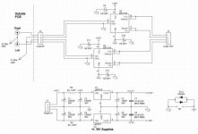
I'm about to design a small DRV134 PCB for my BPA300 amp. This is the schematic, nothing fancy. I included the +/-15V supplies on it. I also included a small CRC filter to drop the amp supply voltage to a lower 20V and goes away with any heatsink on the regulator IC's.
Please comment on this schematic and how can I improve it, or correct my mistakes, before I design the pcb.
Thanks...
Please comment on this schematic and how can I improve it, or correct my mistakes, before I design the pcb.
Thanks...
Attachments
Yes, I got them already so... Digikey has almost 540 in stock for the moment.
Here a possible improvement. Reading the DRV134 specs sheet, it is mentionned that a 10uF coupling cap can be connected as part of the DRV134 loop using the remote sense pins. This way the cap effect is mostly removed from the line. I included the sense pins on the output socket so they can be connected directly to the DRV150 pcb coupling cap. If not needed, they could be jumped using some jumper pads on the PCB.
Here a possible improvement. Reading the DRV134 specs sheet, it is mentionned that a 10uF coupling cap can be connected as part of the DRV134 loop using the remote sense pins. This way the cap effect is mostly removed from the line. I included the sense pins on the output socket so they can be connected directly to the DRV150 pcb coupling cap. If not needed, they could be jumped using some jumper pads on the PCB.
Attachments
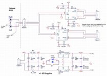
I included the sense pins on the output socket so they can be connected directly to the DRV150 pcb coupling cap.
The loop length would then be quite long...
- Status
- This old topic is closed. If you want to reopen this topic, contact a moderator using the "Report Post" button.
- Home
- Amplifiers
- Chip Amps
- Driver chips for BPA300 amplifier